![CAD Forum - tips, tricks, discussion and utilities for AutoCAD, Inventor, Revit and other Autodesk products [www.cadforum.cz]](/common/arkance_186.png "CAD Forum - ARKANCE Community - tips, tricks, discussion and utilities for AutoCAD, Inventor, Revit and other Autodesk products [www.cadforum.cz]")
CAD FORUM - TIPS & TRICKS | UTILITIES | DISCUSSION | BLOCKS | SUPPORT | HELP & ADVICE

Over 1.127.000 registered users (EN+CZ).
AutoCAD tips, Inventor tips, Revit tips, Civil tips, Fusion tips.
The new Beam calculator, Spirograph generator and Regression curves in the Converters section.
New AutoCAD 2027 commands and sys.variables


 Discussion forum
?CAD discussions, advices, exchange of experience
 CAD discussion forum - ask any CAD-related questions here, share your CAD knowledge on AutoCAD, Inventor, Revit and other Autodesk software with your peers from all over the world. To start a new topic, choose an appropriate forum.
Please abide by the rules of this forum.
This is a peer-to-peer forum. The forum doesn't replace the official direct technical support provided by ARKANCE for its customers.
How to post questions: register or login, go to the specific forum and click the NEW TOPIC button.


|
 Orthographic To Isometric
Post Reply 
|
Page 12> |
| Author | |
curtie 
Groupie 
Joined: 06.Jun.2013 Location: South Africa Using: Autocad 2013 Status: Offline Points: 39 |
 Topic: Orthographic To Isometric Topic: Orthographic To IsometricPosted: 25.Mar.2014 at 19:35 |
|
Hi Guys
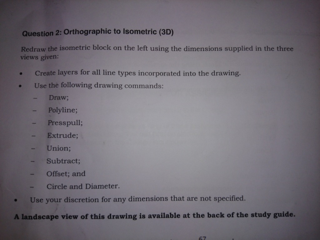
I'm struggling to draw the top part of this drawing, the part that is just above the circle. Please help uploads/380818/Orthographicsmallpdf.com.pdf |
|
|
sean
|
|
 |
|
|
philippe JOSEPH
Senior Member 
Joined: 14.Mar.2011 Location: France Using: AutoCAD Mechanical 2017 Status: Offline Points: 1525 |
Posted: 25.Mar.2014 at 20:33 |
|
Hello curtie, I suppose that your problem is with 3D, not 2D.
Please note that your 3 2D views are located in the european projection. I don't find the width of the embossment R35/R30.  If we suppose that the little embossment 42x28+hole Ă 12 length 67 is on the middle of the unknown width embossment then that embossment width could be 10+28+10 = 48. Edited by philippe JOSEPH - 25.Mar.2014 at 21:25 |
|
|
|
|
John Connor
Senior Member
Joined: 01.Feb.2011 Location: United States Using: AutoCAD 2018 Status: Offline Points: 7175 |
Posted: 25.Mar.2014 at 21:45 |
|
The OP is looking to draw an isometric view of the object in 2D.
If you want to take the easy way construct the object in 3D then use the BASEVIEW or VIEWBASE command (depending on how you access it) to create the top, front, side and one isometric views in 2D. That method makes the most sense. Be advised that the 2D views will be created in a layout and not in model space. If you want model space 2D views use FLATSHOT. Edited by John Connor - 25.Mar.2014 at 21:49 |
|
|
"Humans have a strength that cannot be measured. This is John Connor. If you are reading this, you are the resistance."
<<AutoCAD 2015>> |
|
|
|
|
philippe JOSEPH
Senior Member
Joined: 14.Mar.2011 Location: France Using: AutoCAD Mechanical 2017 Status: Offline Points: 1525 |
Posted: 27.Mar.2014 at 13:01 |
|
Hello curtie anf John, some of you answers are in the DWG file loaded today : ORTHO-TO-ISO_01_A.dwg that you will find in the CAD Blocks library.
|
|
|
|
|
John Connor
Senior Member
Joined: 01.Feb.2011 Location: United States Using: AutoCAD 2018 Status: Offline Points: 7175 |
Posted: 27.Mar.2014 at 13:33 |
|
Nice work Philippe.
|
|
|
"Humans have a strength that cannot be measured. This is John Connor. If you are reading this, you are the resistance."
<<AutoCAD 2015>> |
|
|
|
|
philippe JOSEPH
Senior Member
Joined: 14.Mar.2011 Location: France Using: AutoCAD Mechanical 2017 Status: Offline Points: 1525 |
Posted: 27.Mar.2014 at 13:50 |
|
Hello John, I've tried to compile all the information necessary to do the iso view by the "old way" but I've done it with a flatshot of the 3D object.
Incredilbly, when I take a look at the numbers of my files downloaded from the Cad Blocks library in the site, the uggly file that I've done for a cad discussion about isometric drawing is N° 2 ( and the number 1 is only a compile of shakles from The CROSBY GROUP that I have arranged in 1 file with dimensions and texts ).
I have noticed that maybe 10% of us are working with AutoCAD 3D ( with the number of my 3D files downloaded ).
I'm not making developpment on 3D drawing to "fabricate" parts ( my job is methods ) but I find very interresting functions in AutoCAD 3D ( for my job ) including topo survey, masses and COG, etc...
|
|
|
|
|
John Connor
Senior Member
Joined: 01.Feb.2011 Location: United States Using: AutoCAD 2018 Status: Offline Points: 7175 |
Posted: 27.Mar.2014 at 14:05 |
|
I understand why a student might need to know how 2D isometric drawings were done previous to the introduction of CAD but nowadays teachers of AutoCAD should be instructing their students in how to create 3D models then deriving the 2D views from the model. It makes more sense.
|
|
|
"Humans have a strength that cannot be measured. This is John Connor. If you are reading this, you are the resistance."
<<AutoCAD 2015>> |
|
|
|
|
curtie
Groupie
Joined: 06.Jun.2013 Location: South Africa Using: Autocad 2013 Status: Offline Points: 39 |
Posted: 28.Mar.2014 at 09:21 |
|
|
|
sean
|
|
|
|
|
curtie
Groupie
Joined: 06.Jun.2013 Location: South Africa Using: Autocad 2013 Status: Offline Points: 39 |
Posted: 28.Mar.2014 at 09:25 |
|
Hi Guys
Thanks for all the replies. that is the question I have posted. The snap has to be set to isometric cause I noticed that that's the only time I can use the extrusion tool.
|
|
|
sean
|
|
|
|
|
philippe JOSEPH
Senior Member
Joined: 14.Mar.2011 Location: France Using: AutoCAD Mechanical 2017 Status: Offline Points: 1525 |
Posted: 28.Mar.2014 at 10:32 |
|
Hello curtie, so you had to do the 3D object and show it in a 3D isometric view.
That includes the knowledge of 3D views and use of UCS. Now it would be fun ( joke ) to try and do some dimensionning on the 3D object. Please let us see your 3D object and eventually the presentation that you made of it in a viewport ( if you choose a scale you can have a "scalable" result within the isometrics rules. In the DWG file that I have uploaded I choose to redraw 3 blocks showing the 3 2D views, did you do this or directly made your 3D object ?
|
|
|
|
 Topic Options
|
Post Reply
|
Page 12> |
 Tweet
Tweet
|
| Forum Jump | Forum Permissions You cannot post new topics in this forum You cannot reply to topics in this forum You cannot delete your posts in this forum You cannot edit your posts in this forum You cannot create polls in this forum You cannot vote in polls in this forum |
This page was generated in 0,109 seconds.

CADforum
Tips and tricks, support, utilities, help, discussions on AutoCAD, LT, Inventor, Revit, Map, Civil 3D, 3ds Max, Fusion, Forma, Vault, PowerMill and other Autodesk software (community support by ARKANCE). See About CADforum.
Copyright © 2026 | Advertise with us | Online privacy
