Over 1.110.000 registered users (EN+CZ).
AutoCAD tips, Inventor tips, Revit tips, Civil tips, Fusion tips.
The new Beam calculator and Spirograph generator in the Converters section.
 Discussion forum
?CAD discussions, advices, exchange of experience
 CAD discussion forum - ask any CAD-related questions here, share your CAD knowledge on AutoCAD, Inventor, Revit and other Autodesk software with your peers from all over the world. To start a new topic, choose an appropriate forum.
Please abide by the rules of this forum.
This is a peer-to-peer forum. The forum doesn't replace the official direct technical support provided by ARKANCE for its customers.
How to post questions: register or login, go to the specific forum and click the NEW TOPIC button.
|
Post Reply 
|
Post Reply 
|
|
|
Tweet
|
| Forum Jump | Forum Permissions  You cannot post new topics in this forum You cannot reply to topics in this forum You cannot delete your posts in this forum You cannot edit your posts in this forum You cannot create polls in this forum You cannot vote in polls in this forum |
This page was generated in 0,141 seconds.
![CAD Forum - tips, tricks, discussion and utilities for AutoCAD, Inventor, Revit and other Autodesk products [www.cadforum.cz] CAD Forum - tips, tricks, discussion and utilities for AutoCAD, Inventor, Revit and other Autodesk products [www.cadforum.cz]](/common/arkance_186.png)


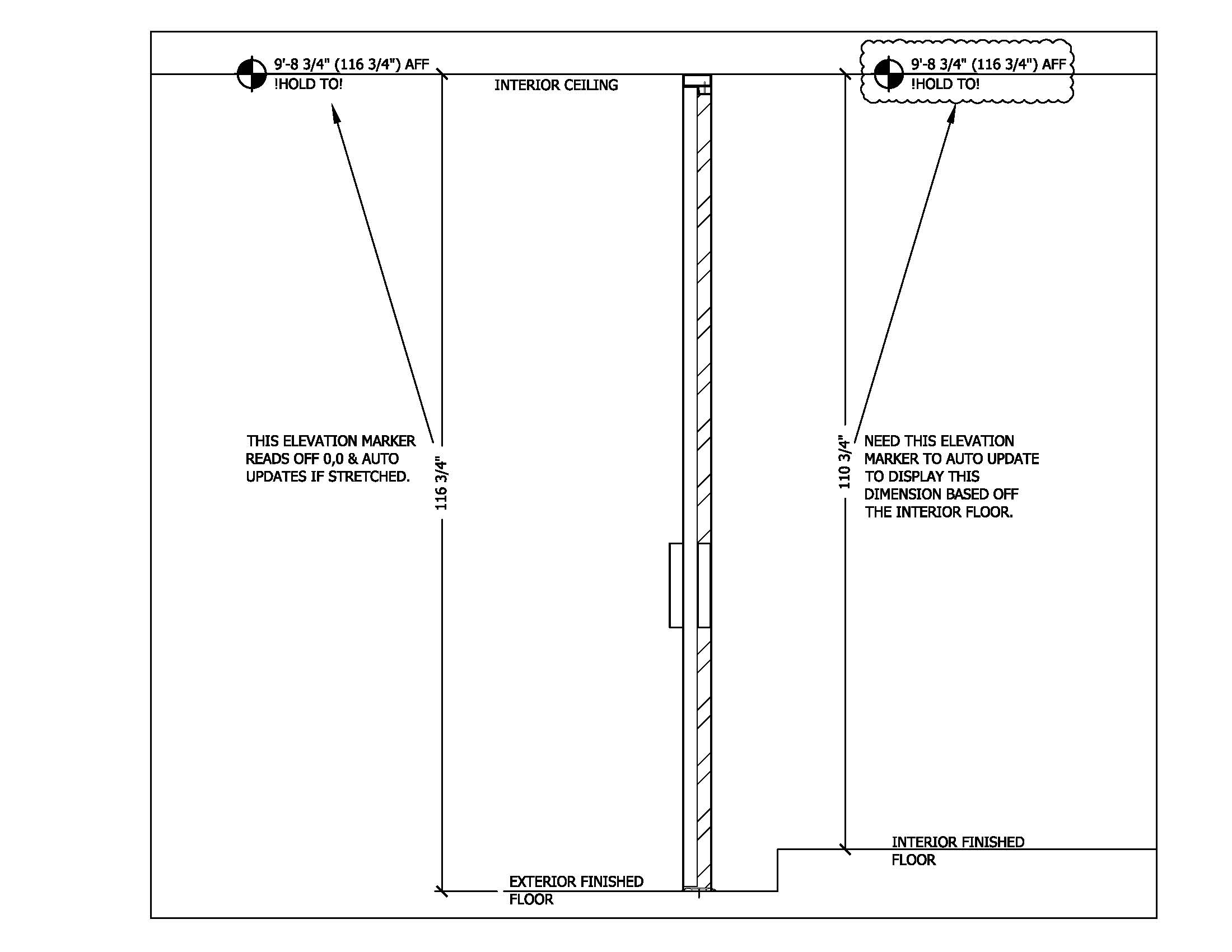
 Placing Elevation Marker with multiple baselines
 Topic Options


