
CAD discussion forum - ask any CAD-related questions here, share your CAD knowledge on AutoCAD, Inventor, Revit and other Autodesk software with your peers from all over the world. To start a new topic, choose an appropriate forum.
Please abide by the
rules of this forum.
How to post questions: register or login, go to the specific forum and click the NEW TOPIC button.
| Author |
 Topic Search Topic Search  Topic Options Topic Options
|
Sve87 
Newbie

Joined: 21.Dec.2016
Location: United Kingdom
Using: Autocad 2017
Status: Offline
Points: 7
|
 Topic: Create a table base AutoCAD 2017 for MAC Topic: Create a table base AutoCAD 2017 for MAC
Posted: 21.Dec.2016 at 17:32 |
Hi guys, I'm new here, I hope I don't violate any rules, and registered with the purpose of getting some help with this sketch I've been struggling to do in a few days. So what I'm basically trying to do is get the exact angles and measurements of the base of this table. I am in a dead end. So I will appreciate some help and someone do it for me. I know it's a really simple job, but I am total beginner. So here are some pics of the table: https://www.arredamento.it/tavoli-in-legno-grezzo_NG4.jpg http://www.italianarredo.it/wp-content/uploads/2014/02/p-24546-shangai-base.jpg What I can't do is to do the the "legs" on top and bottom to be at the same plane
Regards, Sve
|
 |
John Connor
Senior Member

Joined: 01.Feb.2011
Location: United States
Using: AutoCAD 2018
Status: Offline
Points: 7175
|
Posted: 21.Dec.2016 at 17:38 |
|
Well basically you just need two legs...one for each direction then mirror them. As for actually constructing them so that the bottom of each leg and the top of each leg is at the same elevation you can use some temporary construction lines to keep everything in check.
Keep in mind that each leg passes over one leg and under another (like weaving).
Another way to do it would be to construct the four legs but make them longer than they need to be. Then use the SLICE command and one of its several options (ex. - Surface or Object) to slice off the ends of the legs so they are all at the same level.
Edited by John Connor - 21.Dec.2016 at 18:21
|
|
"Humans have a strength that cannot be measured. This is John Connor. If you are reading this, you are the resistance."
<<AutoCAD 2015>>
|
|
Sve87
Newbie
Joined: 21.Dec.2016
Location: United Kingdom
Using: Autocad 2017
Status: Offline
Points: 7
|
Posted: 21.Dec.2016 at 18:36 |
Thanks for the fast reply mate! I thought it would be better to start off with the centre "console" and graze the legs around it. The second option you suggest seems better to me, though I still can't achieve that effect 
|
|
John Connor
Senior Member
Joined: 01.Feb.2011
Location: United States
Using: AutoCAD 2018
Status: Offline
Points: 7175
|
Posted: 21.Dec.2016 at 18:40 |
|
Well the centre console at least helps you position the legs as far as spacing goes but you still need to account for the over/under affect of the legs. Personally that may be the more difficult part of the problem to solve (trial and error). Getting the bottoms and tops of the legs at their respective planes shouldn't be all that difficult if you use the SLICE command as suggested.
|
|
"Humans have a strength that cannot be measured. This is John Connor. If you are reading this, you are the resistance."
<<AutoCAD 2015>>
|
|
Sve87
Newbie
Joined: 21.Dec.2016
Location: United Kingdom
Using: Autocad 2017
Status: Offline
Points: 7
|
Posted: 21.Dec.2016 at 19:16 |
|
I'll give a couple of tries, though if I can't do it would it be possible for you to just outline them roughly so I can start from somewhere. Will be much appreciated!!!
|
|
John Connor
Senior Member
Joined: 01.Feb.2011
Location: United States
Using: AutoCAD 2018
Status: Offline
Points: 7175
|
Posted: 21.Dec.2016 at 19:48 |
|
I'm not sure what you mean by outline them?
Is this for a school project?
Do you know if the legs that run the length of the table are parallel to the edge of the table or at an angle. Those would be the two longest legs. If that is the case then it would probably be fairly simple to create the 3D model given the proper construction lines.
Edited by John Connor - 21.Dec.2016 at 20:05
|
|
"Humans have a strength that cannot be measured. This is John Connor. If you are reading this, you are the resistance."
<<AutoCAD 2015>>
|
|
John Connor
Senior Member
Joined: 01.Feb.2011
Location: United States
Using: AutoCAD 2018
Status: Offline
Points: 7175
|
Posted: 21.Dec.2016 at 20:14 |
Here is my version. The legs running the length of the table are parallel to the edges. The shorter legs have been rotated 30 degrees. 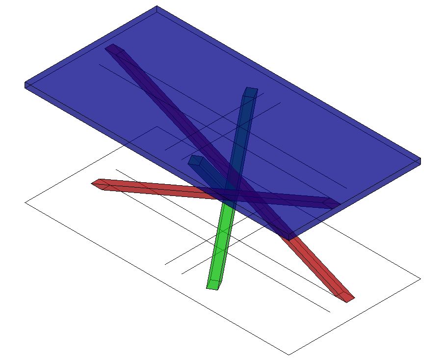
|
|
"Humans have a strength that cannot be measured. This is John Connor. If you are reading this, you are the resistance."
<<AutoCAD 2015>>
|
|
John Connor
Senior Member
Joined: 01.Feb.2011
Location: United States
Using: AutoCAD 2018
Status: Offline
Points: 7175
|
Posted: 21.Dec.2016 at 20:18 |
|
The legs pictured above do indeed go over/under each other. BTW...I used the X-Ray visual style.
Given that you are in the U.K. and about 5 hours ahead of me it must be after 7 p.m. By the time I arrive at work tomorrow it will be around 10 a.m. your time. At some point our paths will cross again. Until then it is almost time for me to take a very long drive home. I'll check this thread tomorrow morning. Good luck. It isn't as tough as it may look.
Thursday morning here. No response? Oh well.
Just wanted to mention I did not use the SLICE command to create my legs. I merely extruded a rectangle along the path of a sloped line.
Edited by John Connor - 22.Dec.2016 at 11:29
|
|
"Humans have a strength that cannot be measured. This is John Connor. If you are reading this, you are the resistance."
<<AutoCAD 2015>>
|
|
Sve87
Newbie
Joined: 21.Dec.2016
Location: United Kingdom
Using: Autocad 2017
Status: Offline
Points: 7
|
Posted: 22.Dec.2016 at 20:41 |
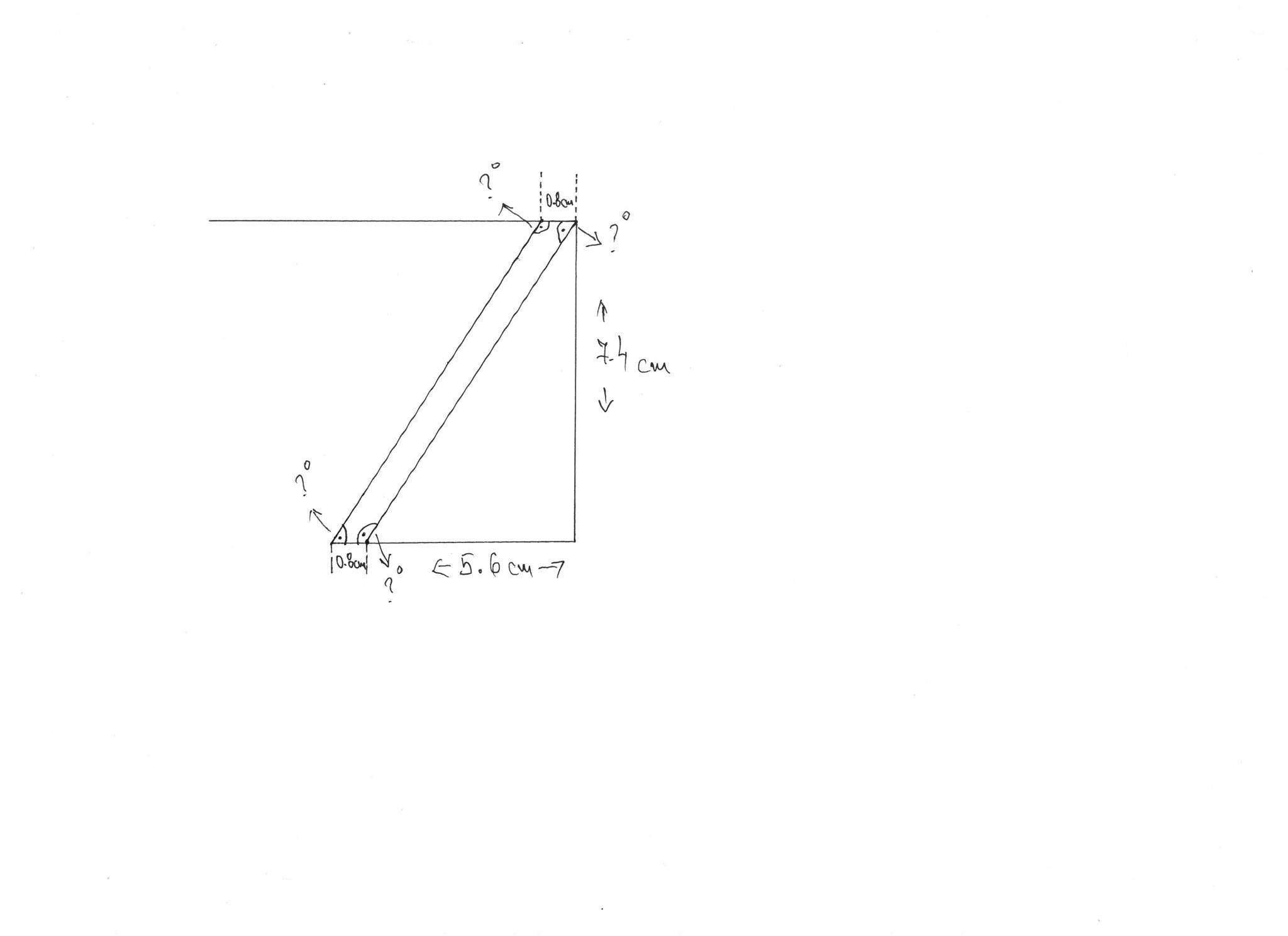
Hey Connor huge thanks for the help!!! I'm still struggling with the 2D version though. So, basically, what I'm trying to find out is the exact degrees of the corners/angles that form up at the top and the bottom. I'm uploading a quick sketch with horizontal and vertical lengths and with the width of the "leg" pointing out with questions marks what I'm looking for. Up until now I couldn't manage to wrap it up, I know it's probably 5min job, but I am a total noob 
Edited by Sve87 - 22.Dec.2016 at 20:42
|
|
John Connor
Senior Member
Joined: 01.Feb.2011
Location: United States
Using: AutoCAD 2018
Status: Offline
Points: 7175
|
Posted: 23.Dec.2016 at 00:15 |
|
Looks like something you could easily draw in AutoCAD either in 2D or 3D. Personally, I don't see what's stopping you from doing it. Draw what you have pictured above in 2D using AutoCAD and derive the lengths and angles of any lines that you require the information for.
Edited by John Connor - 23.Dec.2016 at 00:21
|
|
"Humans have a strength that cannot be measured. This is John Connor. If you are reading this, you are the resistance."
<<AutoCAD 2015>>
|
|


 Discussion forum


 Create a table base AutoCAD 2017 for MAC

 Tweet
Tweet
