
CAD discussion forum - ask any CAD-related questions here, share your CAD knowledge on AutoCAD, Inventor, Revit and other Autodesk software with your peers from all over the world. To start a new topic, choose an appropriate forum.
Please abide by the
rules of this forum.
How to post questions: register or login, go to the specific forum and click the NEW TOPIC button.
| Author |
 Topic Search Topic Search  Topic Options Topic Options
|
Kent Cooper 
Senior Member

Joined: 12.Mar.2013
Location: United States
Using: AutoCAD2020, 2023
Status: Offline
Points: 628
|
 Posted: 16.Oct.2018 at 20:41 Posted: 16.Oct.2018 at 20:41 |
 philippe JOSEPH wrote: philippe JOSEPH wrote:
...I suppose that THICKEN is what Kent what waiting for or his next step.
|
Yes, it is [a newer command than the version of AutoCAD I used for years, so I wasn't aware of it]. BUT if the small difference matters, THICKEN goes only one way from a Surface, with no center-the-thickness option -- it's not like giving a Polyline width [which is centered]. So if the thickness of the ribbon needs to be centered across the zero-thickness twisting Surface, I think it's necessary to LOFT from one Helix to the other, and also LOFT in the other order [from the other to the one], and THICKEN both of the Surfaces by half the desired total thickness, then UNION the two Solid results together [and Erase the Surfaces if you like, if DELOBJ wasn't set to do that in the process of Thickening].
|
 |
philippe JOSEPH
Senior Member
Joined: 14.Mar.2011
Location: France
Using: AutoCAD Mechanical 2017
Status: Offline
Points: 1426
|
Posted: 15.Oct.2018 at 12:41 |
|
Thanks Sean but I have to work the model to make it look much more like the very first image and also I have simplified the SUBTRACTed notches with a "simple" EXTRUDE of a region along a path like a thread that we can see for example on your image.
|
|
SEANT
Groupie

Joined: 09.Jan.2012
Location: United States
Using: AutoCAD 2016
Status: Offline
Points: 31
|
Posted: 15.Oct.2018 at 10:38 |
|
Nicely done.
|
|
philippe JOSEPH
Senior Member
Joined: 14.Mar.2011
Location: France
Using: AutoCAD Mechanical 2017
Status: Offline
Points: 1426
|
Posted: 15.Oct.2018 at 07:43 |
 HOC ERAT IN VOTIS, but different.
Edited by philippe JOSEPH - 15.Oct.2018 at 08:02
|
|
John Connor
Senior Member
Joined: 01.Feb.2011
Location: United States
Using: AutoCAD 2018
Status: Offline
Points: 7175
|
Posted: 13.Oct.2018 at 13:55 |
|
Very nicely done and explained SEANT.
|
|
"Humans have a strength that cannot be measured. This is John Connor. If you are reading this, you are the resistance."
<<AutoCAD 2015>>
|
|
SEANT
Groupie
Joined: 09.Jan.2012
Location: United States
Using: AutoCAD 2016
Status: Offline
Points: 31
|
Posted: 13.Oct.2018 at 11:43 |
philippe JOSEPH wrote:
Seant you are number "ONE", tell us more !!!!!!!!!!!!Eventually a "step by step" drawing ? I suppose that LOFT is like Kent's method : LOFT between 2 concentric helixes, and then ... I suppose that THICKEN is what Kent what waiting for or his next step.
|
That's correct.
I think the "Step by Step" would best be done by each individual. I can tell you it's possible, you tell me what your specific steps were. Experimenting is where we find the capabilities, and limitations, of AutoCAD.
|
|
philippe JOSEPH
Senior Member
Joined: 14.Mar.2011
Location: France
Using: AutoCAD Mechanical 2017
Status: Offline
Points: 1426
|
Posted: 13.Oct.2018 at 11:05 |
Seant you are number "ONE", tell us more !!!!!!!!!!!! Eventually a "step by step" drawing ? I suppose that LOFT is like Kent's method : LOFT between 2 concentric helixes, and then ... I suppose that THICKEN is what Kent what waiting for or his next step.
Edited by philippe JOSEPH - 13.Oct.2018 at 11:07
|
|
SEANT
Groupie
Joined: 09.Jan.2012
Location: United States
Using: AutoCAD 2016
Status: Offline
Points: 31
|
Posted: 13.Oct.2018 at 10:58 |
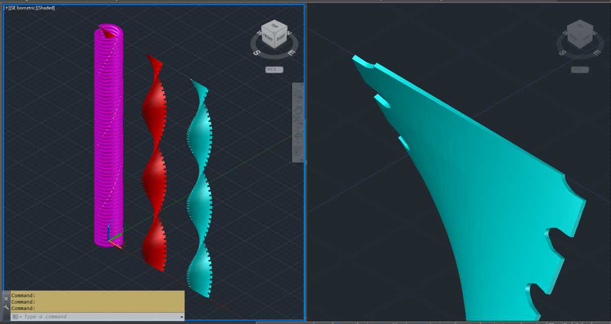
A sequence of commands: Helix Loft Sweep Subtract Thicken
Results.
|
|
philippe JOSEPH
Senior Member
Joined: 14.Mar.2011
Location: France
Using: AutoCAD Mechanical 2017
Status: Offline
Points: 1426
|
Posted: 12.Oct.2018 at 19:44 |
|
Or maybe we are going to loose our mind because Arunvigneshram is just teasing us with his Solidworks ans we are working with AutoCAD and not Inventor or an other product.
Edited by philippe JOSEPH - 12.Oct.2018 at 20:02
|
|
Kent Cooper
Senior Member
Joined: 12.Mar.2013
Location: United States
Using: AutoCAD2020, 2023
Status: Offline
Points: 628
|
Posted: 12.Oct.2018 at 19:08 |
philippe JOSEPH wrote:
... I would use the LOFT command between 2 rectangles correctly located in 3D ....
|
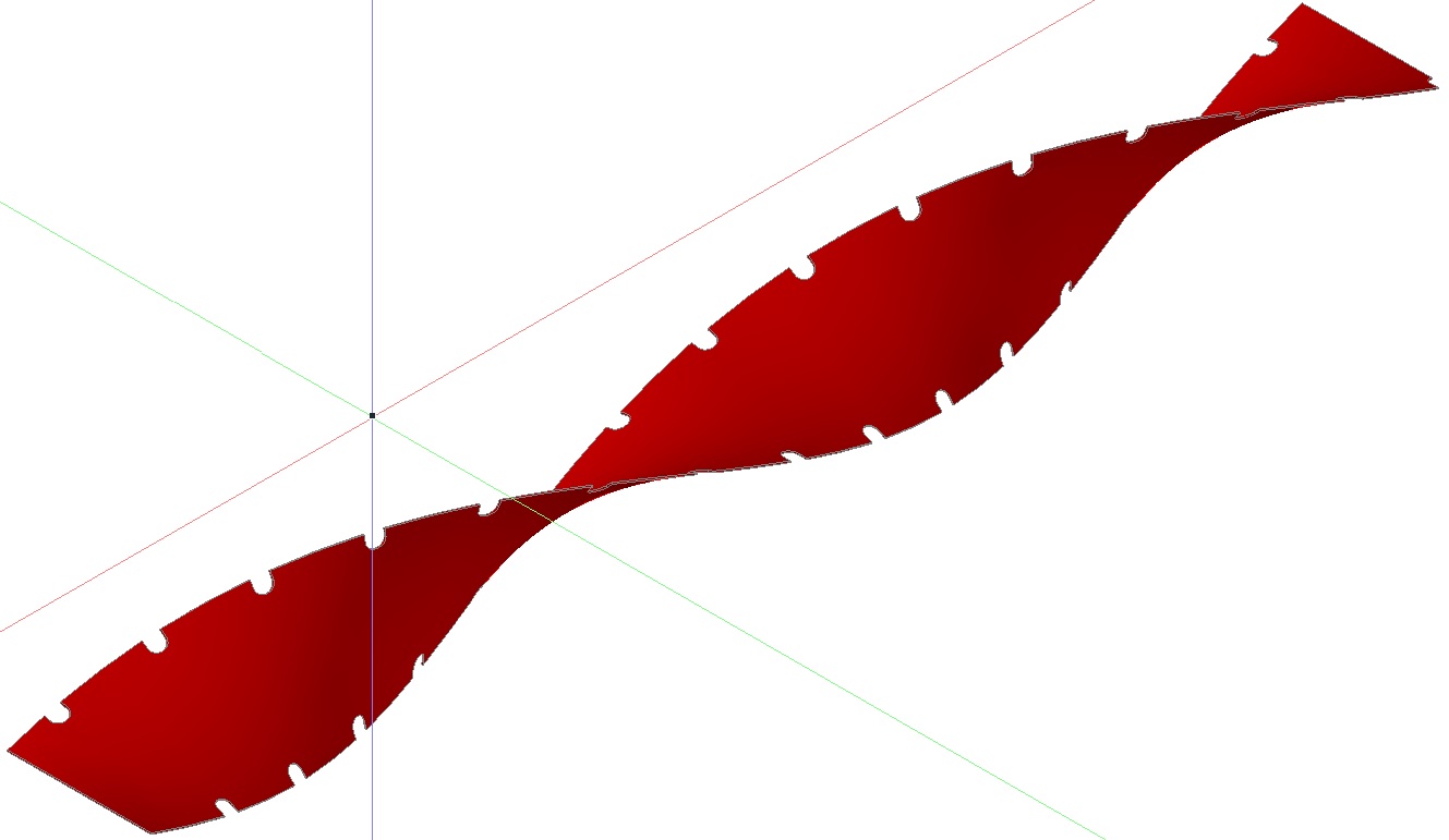
Not between just 2 of them, but an approach that worked for me was to draw a long skinny rectangle, copy it upward multiple times, rotate each copy successively more to create the twist, and then LOFT through the stack of them. I did them at a distance apart about the same as the length of the rectangle, and at 30-degree successive rotations -- I don't know how large the angle can be and still work right, but 90-degree rotation gave a very different kind of result. That gives a real Solid, rather than a Surface as in my previous reply. What I haven't found a good way to do yet is to position little Solids appropriately for Subtracting to make the notches -- ARRAYPATH seems likely, but I haven't found the right combination of options and initial orientation to get them to align in the right way.
|
|


 Discussion forum


 Modeling a Twisted Ribbon

 Tweet
Tweet
