
CAD discussion forum - ask any CAD-related questions here, share your CAD knowledge on AutoCAD, Inventor, Revit and other Autodesk software with your peers from all over the world. To start a new topic, choose an appropriate forum.
Please abide by the
rules of this forum.
How to post questions: register or login, go to the specific forum and click the NEW TOPIC button.
| Author |
 Topic Search Topic Search  Topic Options Topic Options
|
SEANT 
Groupie

Joined: 09.Jan.2012
Location: United States
Using: AutoCAD 2016
Status: Offline
Points: 31
|
 Posted: 13.Oct.2018 at 11:43 Posted: 13.Oct.2018 at 11:43 |
 philippe JOSEPH wrote: philippe JOSEPH wrote:
Seant you are number "ONE", tell us more !!!!!!!!!!!!Eventually a "step by step" drawing ? I suppose that LOFT is like Kent's method : LOFT between 2 concentric helixes, and then ... I suppose that THICKEN is what Kent what waiting for or his next step.
|
That's correct.
I think the "Step by Step" would best be done by each individual. I can tell you it's possible, you tell me what your specific steps were. Experimenting is where we find the capabilities, and limitations, of AutoCAD.
|
 |
John Connor
Senior Member

Joined: 01.Feb.2011
Location: United States
Using: AutoCAD 2018
Status: Offline
Points: 7175
|
Posted: 13.Oct.2018 at 13:55 |
|
Very nicely done and explained SEANT.
|
|
"Humans have a strength that cannot be measured. This is John Connor. If you are reading this, you are the resistance."
<<AutoCAD 2015>>
|
|
philippe JOSEPH
Senior Member
Joined: 14.Mar.2011
Location: France
Using: AutoCAD Mechanical 2017
Status: Offline
Points: 1426
|
Posted: 15.Oct.2018 at 07:43 |
 HOC ERAT IN VOTIS, but different.
Edited by philippe JOSEPH - 15.Oct.2018 at 08:02
|
|
SEANT
Groupie
Joined: 09.Jan.2012
Location: United States
Using: AutoCAD 2016
Status: Offline
Points: 31
|
Posted: 15.Oct.2018 at 10:38 |
|
Nicely done.
|
|
philippe JOSEPH
Senior Member
Joined: 14.Mar.2011
Location: France
Using: AutoCAD Mechanical 2017
Status: Offline
Points: 1426
|
Posted: 15.Oct.2018 at 12:41 |
|
Thanks Sean but I have to work the model to make it look much more like the very first image and also I have simplified the SUBTRACTed notches with a "simple" EXTRUDE of a region along a path like a thread that we can see for example on your image.
|
|
Kent Cooper
Senior Member
Joined: 12.Mar.2013
Location: United States
Using: AutoCAD2020, 2023
Status: Offline
Points: 626
|
Posted: 16.Oct.2018 at 20:41 |
philippe JOSEPH wrote:
...I suppose that THICKEN is what Kent what waiting for or his next step.
|
Yes, it is [a newer command than the version of AutoCAD I used for years, so I wasn't aware of it]. BUT if the small difference matters, THICKEN goes only one way from a Surface, with no center-the-thickness option -- it's not like giving a Polyline width [which is centered]. So if the thickness of the ribbon needs to be centered across the zero-thickness twisting Surface, I think it's necessary to LOFT from one Helix to the other, and also LOFT in the other order [from the other to the one], and THICKEN both of the Surfaces by half the desired total thickness, then UNION the two Solid results together [and Erase the Surfaces if you like, if DELOBJ wasn't set to do that in the process of Thickening].
|
|
philippe JOSEPH
Senior Member
Joined: 14.Mar.2011
Location: France
Using: AutoCAD Mechanical 2017
Status: Offline
Points: 1426
|
Posted: 17.Oct.2018 at 07:13 |
|
I have placed my AutoCAD file : Modeling a Twisted Ribbon-01.dwg here in the CAD/BIM Blocks library.
|
|
SEANT
Groupie
Joined: 09.Jan.2012
Location: United States
Using: AutoCAD 2016
Status: Offline
Points: 31
|
Posted: 18.Oct.2018 at 09:53 |
Very nice model, and excellent tutorial.
I see now that your earlier request to me was an opportunity/offer to create the tutorial. This may be a little late but, Thank you.
I'll see if some time presents itself - perhaps I can put something together that has something new to offer.
|
|
SEANT
Groupie
Joined: 09.Jan.2012
Location: United States
Using: AutoCAD 2016
Status: Offline
Points: 31
|
Posted: 18.Oct.2018 at 09:58 |
Kent Cooper wrote:
philippe JOSEPH wrote:
...I suppose that THICKEN is what Kent what waiting for or his next step.
|
Yes, it is [a newer command than the version of AutoCAD I used for years, so I wasn't aware of it]. BUT if the small difference matters, THICKEN goes only one way from a Surface, with no center-the-thickness option -- it's not like giving a Polyline width [which is centered]. So if the thickness of the ribbon needs to be centered across the zero-thickness twisting Surface, I think it's necessary to LOFT from one Helix to the other, and also LOFT in the other order [from the other to the one], and THICKEN both of the Surfaces by half the desired total thickness, then UNION the two Solid results together [and Erase the Surfaces if you like, if DELOBJ wasn't set to do that in the process of Thickening]. |
Good point. If I do find the time to create a version of a tutorial, I'll keep accuracy in mind.
|
|
SEANT
Groupie
Joined: 09.Jan.2012
Location: United States
Using: AutoCAD 2016
Status: Offline
Points: 31
|
Posted: 18.Oct.2018 at 10:09 |
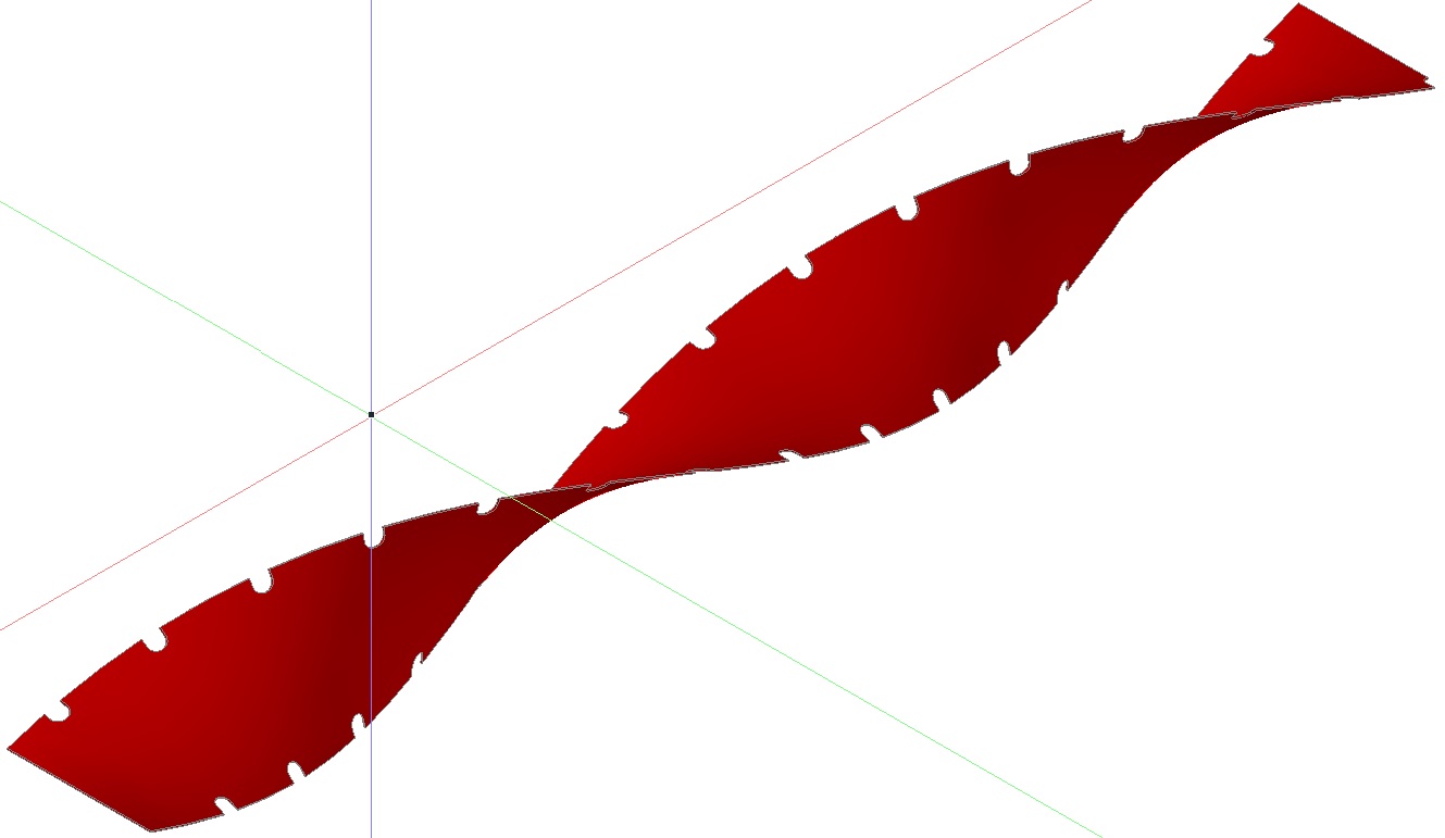
I suppose keeping a mind towards accuracy requires hard parameters. The OP (Arunvigneshram) had a picture, and a description of a strip of metal inserted into a pipe. A new tutorial should make use of philippe's dimensions - a 20 mm inside diameter pipe @ 180 mm long with a .2 mm thick strip with one twist.
I'll see what I can do.
Edited by SEANT - 18.Oct.2018 at 10:17
|
|


 Discussion forum


 Modeling a Twisted Ribbon
 Tweet
Tweet
