CAD Forum - Database of tips, tricks and utilities for AutoCAD, Inventor and other Autodesk products [www.cadforum.cz]
CZ | EN | DE
Login or
registration
  Visitors: 6456
RSS channel - CAD tips RSS tips
RSS discussions

Discussion Discussion forum


HelpCAD discussion

 
CAD Forum - Homepage CAD discussion forum - ask any CAD-related questions here, share your CAD knowledge on AutoCAD, Inventor, Revit and other Autodesk software with your peers from all over the world. To start a new topic, choose an appropriate forum.

Please abide by the rules of this forum.

How to post questions: register or login, go to the specific forum and click the NEW TOPIC button.
  FAQ FAQ  Forum Search   Events   Register Register  Login Login

Topic ClosedCATIA Drawing export to DXF/DWG

 Post Reply Post Reply
Author
jsq View Drop Down
Newbie
Newbie


Joined: 16.Oct.2021
Location: Poland
Using: CATIA, AutoCAD
Status: Offline
Points: 2
Direct Link To This Post Topic: CATIA Drawing export to DXF/DWG
    Posted: 16.Oct.2021 at 20:14
Hi Everyone
I'm engineer worki in CATIA. A part of my projects are cuted on CNC machines (wood or metal).
In that case I need to export some shapes to DXF format, and I need to open it in AutoCAD and convert to closed polyline
for CNC machine program.
The problem appears when there are some arcs, rounded corners ets.
In DXF the end points of each arc are disconnected from the neighboring lines. The distance is very, very small, like 0,00000105mm!
I lost a lot of time for manually connect these breaks to achieve shape ready to convert to closed polyline (I using _pedit command).


Can anyone knows how to improve this work?

I have checked options in CATIA. Each time with the same result.

Maybe there's some option in AutoCAD for ignoring such small distances?
Back to Top
philippe JOSEPH View Drop Down
Senior Member
Senior Member


Joined: 14.Mar.2011
Location: France
Using: AutoCAD Mechanical 2017
Status: Offline
Points: 1426
Direct Link To This Post Posted: 17.Oct.2021 at 08:16
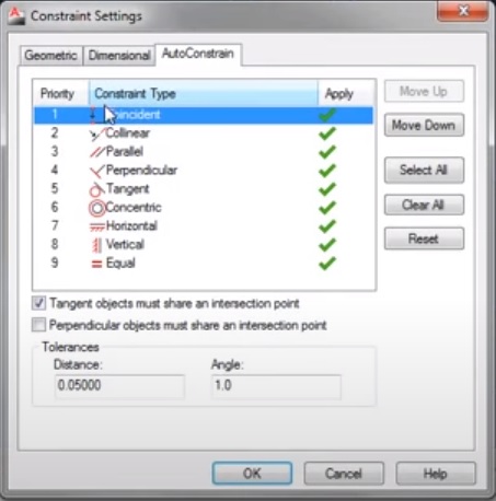
Hello jsq, you can "close" shapes with Geometric Constraints :


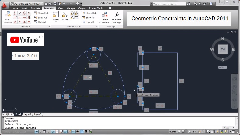
Also see this video on the internet :

Geometric Constraints in AutoCAD 2011
See about : Tolerances set to zero ( 0 ) in distances, Autoconstrain that will do the job on selected items.
It can even "sraiten" some geometry with the Angle tolerance set to zero ( 0 ), be carefull with these 2 settings working at the same time. 


Edited by philippe JOSEPH - 17.Oct.2021 at 08:27
Back to Top
philippe JOSEPH View Drop Down
Senior Member
Senior Member


Joined: 14.Mar.2011
Location: France
Using: AutoCAD Mechanical 2017
Status: Offline
Points: 1426
Direct Link To This Post Posted: 17.Oct.2021 at 08:21
Back to Top
philippe JOSEPH View Drop Down
Senior Member
Senior Member


Joined: 14.Mar.2011
Location: France
Using: AutoCAD Mechanical 2017
Status: Offline
Points: 1426
Direct Link To This Post Posted: 17.Oct.2021 at 08:25
Jsq, you can verify if shapes are closed by launching some commands that require those shapes to be closed and AutoCAD will show you were it isn't with some red circles I think : Hatches, Boundary, etc...
Back to Top
philippe JOSEPH View Drop Down
Senior Member
Senior Member


Joined: 14.Mar.2011
Location: France
Using: AutoCAD Mechanical 2017
Status: Offline
Points: 1426
Direct Link To This Post Posted: 17.Oct.2021 at 08:32
Jsq when tou read 0,00000105 mm it's with the maximum precision available on AutoCAD that is 8 digits after the comma, some more can be after this and you can eventually see it by scaling x times your items and read some distances.
For example if you scale an item 1000 times you will see 3 digits more of precision.
Back to Top

Related CAD tips:


 Post Reply Post Reply
  Share Topic   

Forum Jump Forum Permissions View Drop Down


This page was generated in 0,343 seconds.