3D models
Printed From: CAD Forum
Category: EN
Forum Name: AutoCAD
Forum Description: Discussion about AutoCAD and AutoCAD LT, viewers, DWG and DXF formats, Design Review, AutoCAD web, Drive, add-ons
URL: https://www.cadforum.cz/forum_en/forum_posts.asp?TID=10259
Printed Date: 05.Sep.2026 at 02:24
Topic: 3D models
Posted By: bipedaltoolmaker
Subject: 3D models
Date Posted: 01.May.2014 at 20:01
|
I am having an issue creating a 3D model. I am using Autocad 2012 and have a round wire shape that I wish to profile out of a block. When I subtract my wire shape from the block I end up with tunnels where the wire runs below the blocks upper plane. How do I expose those areas? ------------- Nobody looks good with brown lipstick on |
Replies:
Posted By: bipedaltoolmaker
Date Posted: 01.May.2014 at 20:06
|
Oh, I also have no wire centerline, I am working from a supplied solid model from an unknown software. So I have not been able to sweep a modified wire shape. ------------- Nobody looks good with brown lipstick on |
Posted By: John Connor
Date Posted: 01.May.2014 at 20:11
|
Can you post an image or two? Did you slice the block so you can see the grooves left behind after the wire was subtracted? Is that it? There won't be a wire centerline unless you add it yourself. ------------- "Humans have a strength that cannot be measured. This is John Connor. If you are reading this, you are the resistance." <<AutoCAD 2015>> |
Posted By: bipedaltoolmaker
Date Posted: 01.May.2014 at 21:06
|
I could get in trouble with my boss if I were to post any images, sorry. I am pretty new to 3D, so I did not think to slice it. I will give that a try. I also don't know how to add the centerline other than drawing it from point to point. I can do that on the straight sections easily enough but the curves don't have enough info, just a start and an end with no arc info. I am sure I am missing something simple, but I don't have the experience to know what it is. Thanks for the reply :) ------------- Nobody looks good with brown lipstick on |
Posted By: bipedaltoolmaker
Date Posted: 01.May.2014 at 22:12
|
Attempting "slice', but I need a slice that is a contour match, not linear. Is that possible? What we are attempting to do is create a digital file that can be used in a CAM program to machine a block. The areas that dip down in the Z axis are a problem. They are almost spiral in nature and appear to have been created from a spline. ------------- Nobody looks good with brown lipstick on |
Posted By: John Connor
Date Posted: 02.May.2014 at 11:22
|
Yeah, like I understood any of that. A thousand words sometimes does not make a picture while a picture can be worth a thousand words. Yes, you can make a profile slice. I don't understand how you drew your wire in the first place, unless it were straight (which does not sound like it is) without drawing the centerline then extruding or sweeping a circle along it. Without an image or an actual drawing to work with we are left we no good options. I'm not interested in stealing your idea/design. We probably work in completely different fields anyway. It would be like a surgeon using a John Deere yard tractor to do brain surgery. Ain't happening. Know what I mean? OK...mock something up that kind of shows us what you are facing and we'll use our imagination. Post an image and we'll see where that leads. ------------- "Humans have a strength that cannot be measured. This is John Connor. If you are reading this, you are the resistance." <<AutoCAD 2015>> |
Posted By: John Connor
Date Posted: 02.May.2014 at 13:37
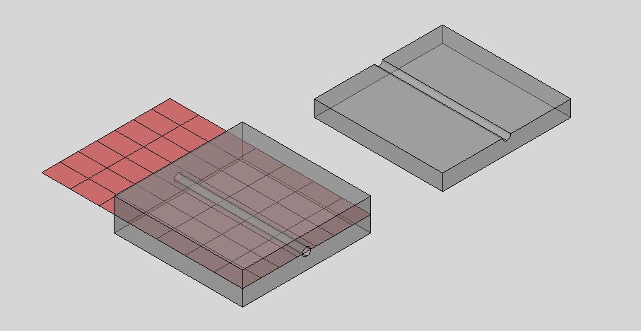 . .One of many possible options is to slice your block using a surface. The block on the left includes an extruded line (resulting in a surface) that will be used in the SLICE command. The block on the right shows the end result. The SLICE command allows the user to keep BOTH or ONE of the sides of the sliced 3D model. ------------- "Humans have a strength that cannot be measured. This is John Connor. If you are reading this, you are the resistance." <<AutoCAD 2015>> |
Posted By: John Connor
Date Posted: 02.May.2014 at 13:42
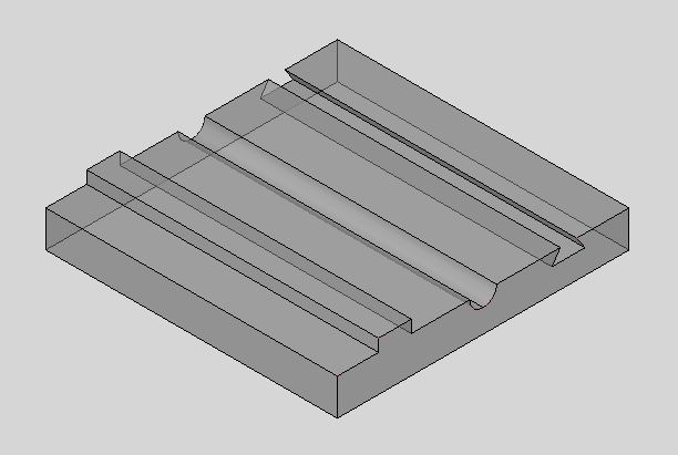 . This block has been sliced with a surface that had a bit of an unusual pattern. ------------- "Humans have a strength that cannot be measured. This is John Connor. If you are reading this, you are the resistance." <<AutoCAD 2015>> |
Posted By: John Connor
Date Posted: 02.May.2014 at 13:47
|
You do have other options. The first that comes to mind is the SECTIONPLANE command. Using this command on a 3D model you can cut sections wherever/however you like. The sections will be 2D blocks. You could also use the SOLVIEW/SOLDRAW commands to create your different views including sections. Unfortunately without a clear picture of what you are working with it is difficult to say with 100% certainty what the best option would be. ------------- "Humans have a strength that cannot be measured. This is John Connor. If you are reading this, you are the resistance." <<AutoCAD 2015>> |
Posted By: bipedaltoolmaker
Date Posted: 05.May.2014 at 21:42
|
Sorry, I understand I am not as clear as I could be. I did not create the geometry, it was supplied by a customer. I ended up copying the shape down in the Z plane, unioning and then doing a subtract. Maybe not the easiest method but it got me what I needed. Thank you for your help, many of your suggestions are things I was unaware of and I did learn from you. Dave ------------- Nobody looks good with brown lipstick on |