loft and polyline
Printed From: CAD Forum
Category: EN
Forum Name: AutoCAD
Forum Description: Discussion about AutoCAD and AutoCAD LT, viewers, DWG and DXF formats, Design Review, AutoCAD web, Drive, add-ons
URL: https://www.cadforum.cz/forum_en/forum_posts.asp?TID=10806
Printed Date: 05.Sep.2026 at 22:23
Topic: loft and polyline
Posted By: joao56777
Subject: loft and polyline
Date Posted: 27.Nov.2014 at 20:02
|
Hi, I'm a mechanical engineer and i work in construction area. Currently i'm working in a dam (barrage) in portugal, and i can't do measure of massproperties (volume) of an block (concrete). I need to calculate all the volume of concrete that i need to do that block. What i do is, copy the bonderies of the dam and paste on side of the real draw (you can see in drawing). Because the growing of the dam is not equal (the width and lenght is not the same in every block) i need to use the loft to calculate the volume. But first i need to erase all the surfaces that growing on his sides. I erase all surfaces and calculate the gross volume, and then, separatly i add all the exterior surfaces. But, i think that i'm doing something that is not right because i do the EXPLODE the polylines, and then SKRETCH to intercept the two sides. I think that when i do the skretch to unite the polylines is not follow the path, and with the loft can see that the grid is not the same (please check). There must be another way to unit the two polylines to follow the path. I tried to get the angle of the arc of the side the dam, and made a new arc, instead put together two polilynes. But i cant get the radius. I Attached the file, but have more than 500kb. Coud you help me? I really need help to make the measuring. Please
|
Replies:
Posted By: John Connor
Date Posted: 28.Nov.2014 at 00:33
|
Upload the drawing to the CAD Blocks area and let us know the name and where you put it exactly. ------------- "Humans have a strength that cannot be measured. This is John Connor. If you are reading this, you are the resistance." <<AutoCAD 2015>> |
Posted By: joao56777
Date Posted: 28.Nov.2014 at 00:52
|
uploads/518478/Bloco_E2-E3_36_120-00_-_36_betonagembloco.dwg4.dwg" rel="nofollow - uploads/518478/Bloco_E2-E3_36_120-00_-_36_betonagembloco.dwg4.dwg I used the command PURGE, and the drawing pass to 250 kb (1Mb) |
Posted By: philippe JOSEPH
Date Posted: 28.Nov.2014 at 07:52
|
Hello JoĂŁo bomdia, for the polylines I recommand to EXTEND and not STRECH them because you will change the polyline.
For AutoCAD 3D you can use commands to generate curves with facets between 2 curves located in 3D and then use these surfaces with facets to generate solids.
Surfaces and solids shouldn't be a problem on dams because the concrete that you will bulit will be like this I think.
Ask for these commands if necessary.
Eventually if you use AutoCAD with a portuguese release take a look at the dictionnary to tranlate the commands in different languages.
|
Posted By: joao56777
Date Posted: 28.Nov.2014 at 12:32
|
HELLO philippe JOSEPH First of all thanks for your's quick answer. I try to do the EXTEND and i got the polylines intercept. But when i JOIN the polylines, i think i have problems, because they don't close all polylines. Mainly in the low bonderie. Did i made something wrong? I dont know any command to generate curves in autocad 3D, and i only work in English autocad . |
Posted By: joao56777
Date Posted: 28.Nov.2014 at 13:01
|
HELLO philippe JOSEPH I do the EXTEND (Edge) and then JOIN and when i made the LOFT do not generate a solid but only 4 surfaces |
Posted By: philippe JOSEPH
Date Posted: 28.Nov.2014 at 14:11
|
Hello again JoĂŁo, I have open your 3D file.
I supose that you want to work with the 2 polylines in the middle "Linha Corte" and "Betao PU303" and I supose that you want to joint them with a 3D solid likr the 3DSOLID layer: "Linha Corte" on the right.
I supose also that the assembly of surfaces and polylines on the left is the result that you want to know the volume.
The 2 polylines in the middle are at elevation "0" and "1.5" exactly so I would do a big solid height 1.5 and add or remove material to have the final result.
In any case do a copy at an exact distance for each 3D modification so that you can go back or modify safely.
Eventually see my file "3D SOLID 01.dwg that you can find in the CAD/BIM Blocks directory here in the site, launch a search with the file name complete or partial name.
To create 3D surfaces between 2 curves located in 3D try : EDGESURF or RULESURF for example.
Please let us know if this helped or not. Also to know : if you LOFT closed surfaces modified with the command REGION you will get solids and not surfaces.
|
Posted By: joao56777
Date Posted: 28.Nov.2014 at 19:21
|
Thanks to reply my answers, This is so simple idea that i didn't remember. I try to do the way that you advice me, with the 1,5 rectangle, but i cant do it, because i cant transform the block (between the betao p303 e linha de corte layers) in a solid. If was simple with no solid out of bounderies of block like the others in the dam, is easy... but since this its all like this difficult way. I think i'm getting wrong in any point... |
Posted By: philippe JOSEPH
Date Posted: 01.Dec.2014 at 09:04
|
Bomdia JoĂŁo, I did a 3D work based on your file, see the steps that I take from 1 to 18.
The result is on step 5.
I had to do 5 files to upload them, rebuilt it by inserting xxxxx-2 to xxxxx-5 in xxxxxxx-1.dwg
tell me if this helped or not.
http://www.cadforum.cz/forum_en/uploads/175428/bloco5-1.dwg" rel="nofollow - uploads/175428/bloco5-1.dwg
http://www.cadforum.cz/forum_en/uploads/175428/bloco5-2.dwg" rel="nofollow - uploads/175428/bloco5-2.dwg
http://www.cadforum.cz/forum_en/uploads/175428/bloco5-3.dwg" rel="nofollow - uploads/175428/bloco5-3.dwg
http://www.cadforum.cz/forum_en/uploads/175428/bloco5-4.dwg" rel="nofollow - uploads/175428/bloco5-4.dwg
http://www.cadforum.cz/forum_en/uploads/175428/bloco5-5.dwg" rel="nofollow - uploads/175428/bloco5-5.dwg
|
Posted By: John Connor
Date Posted: 01.Dec.2014 at 20:12
|
joao: Do you understand what Philippe did or not? ------------- "Humans have a strength that cannot be measured. This is John Connor. If you are reading this, you are the resistance." <<AutoCAD 2015>> |
Posted By: joao56777
Date Posted: 01.Dec.2014 at 22:13
|
Yes, I understand very well :) Its very easy and its right. Thanks for all my friends. |
Posted By: joao56777
Date Posted: 02.Dec.2014 at 02:04
|
Hi, I have another problem with other drawing. With the geometry of this drawing is so easy that only need to use the command LOFT. But i can't JOIN (PEDIT) all polylines to make a SOLID. I only need the volume of all block. I have miss some command, to make this right. that could be easy, i think, but i dont have many experience... Could you help me? uploads/518478/Bloco_E3-E4_41_135-615_-_41_Betonagem.dwg" rel="nofollow - uploads/518478/Bloco_E3-E4_41_135-615_-_41_Betonagem.dwg |
Posted By: philippe JOSEPH
Date Posted: 02.Dec.2014 at 10:10
|
http://www.cadforum.cz/forum_en/uploads/175428/betonagembloco5_PJH.dwg" rel="nofollow - uploads/175428/betonagembloco5_PJH.dwg
Hello JoĂŁo, I will take a look at your drawing but :
Primeiro, verifique a fase 3 do desenho anexado para mim criar as extrusões corretas.
O que tem que fazer com :Rede de Refrigeração - Prumadas à 1 e 1.2 ?
( Eu so frances mas a minha esposa e brasileira ). |
Posted By: John Connor
Date Posted: 02.Dec.2014 at 12:53
|
I'm not understanding why you resort to using LOFT to solve the problem. 95% of what you show could be created as a solid by simply using the Extrude or PressPull command. ------------- "Humans have a strength that cannot be measured. This is John Connor. If you are reading this, you are the resistance." <<AutoCAD 2015>> |
Posted By: philippe JOSEPH
Date Posted: 02.Dec.2014 at 13:41
|
Yes John is wright.
Loft not predictable in his trajectories to create solids in that case.
I am taking a look at your 2nd file but it's difficult to create region to be extruded because the geometry is not 100% flat and after this the solids to add or remove are not so simple.
|
Posted By: John Connor
Date Posted: 02.Dec.2014 at 14:17
|
If you separate the large, almost square, area from the rest of the drawing you'll find that both the top and bottom polylines are indeed flat. ------------- "Humans have a strength that cannot be measured. This is John Connor. If you are reading this, you are the resistance." <<AutoCAD 2015>> |
Posted By: John Connor
Date Posted: 02.Dec.2014 at 16:50
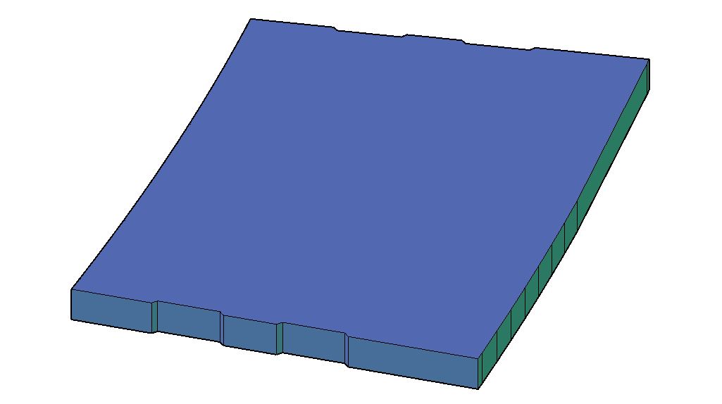 A big portion of your drawing created as a solid using the Extrude command. I'm not sure why you continue to create surfaces first. Please explain. ------------- "Humans have a strength that cannot be measured. This is John Connor. If you are reading this, you are the resistance." <<AutoCAD 2015>> |
Posted By: John Connor
Date Posted: 02.Dec.2014 at 17:10
|
I think the above may be wrong. A closer look at your drawing reveals that the bottom and top linework that form the perimeter of the object are not lined up exactly. Extrude may not be the best command to use although I suspect that Loft will result in surfaces and not a solid. ------------- "Humans have a strength that cannot be measured. This is John Connor. If you are reading this, you are the resistance." <<AutoCAD 2015>> |
Posted By: John Connor
Date Posted: 02.Dec.2014 at 17:19
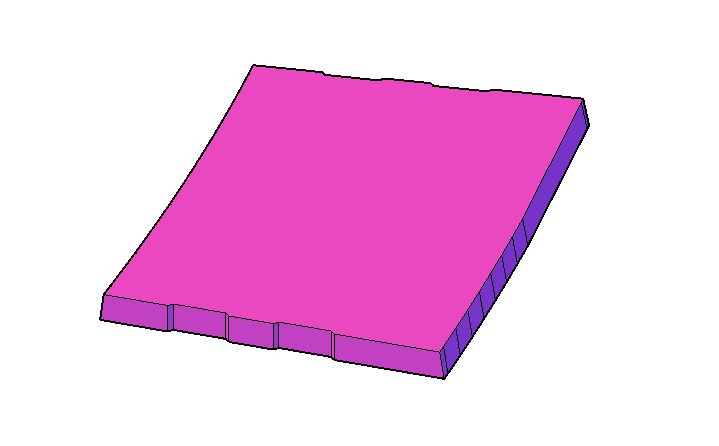 OK...this one is better. I used the Loft command along with the Guides option. Before lofting I drew a 3Dpolyline at each of the four corners starting from the bottom profile to the top profile. I think this one is a keeper. Now to figure out the best way to handle the remainder. ------------- "Humans have a strength that cannot be measured. This is John Connor. If you are reading this, you are the resistance." <<AutoCAD 2015>> |
Posted By: John Connor
Date Posted: 02.Dec.2014 at 17:27
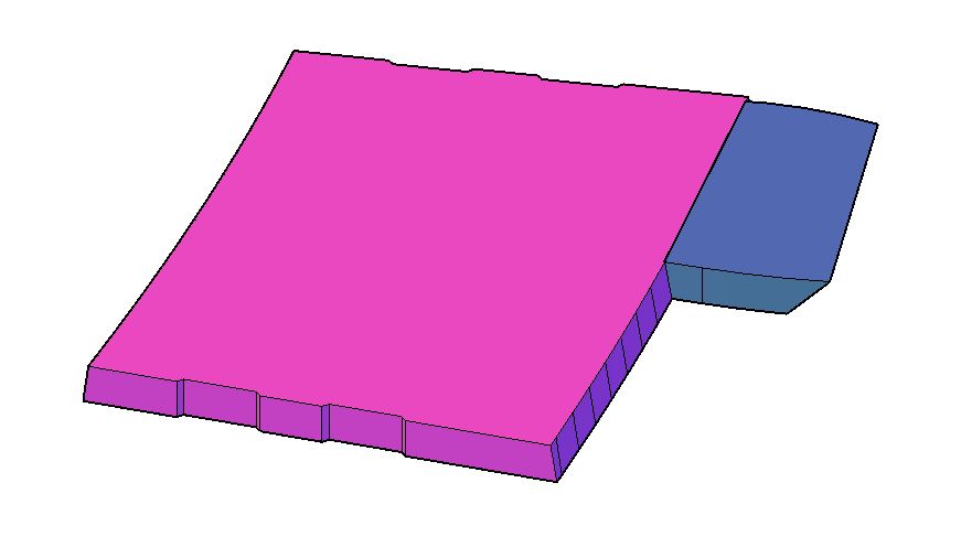 Success. Once again I created two polyline profiles (top and bottom perimeter) and lofted them. No need to use the Guides option either. At this point they just need to be unioned and MASSPROP run on the resultant solid. The second smaller section confused me at first until I realized the sides were slightly curved. ------------- "Humans have a strength that cannot be measured. This is John Connor. If you are reading this, you are the resistance." <<AutoCAD 2015>> |
Posted By: John Connor
Date Posted: 02.Dec.2014 at 17:53
 The finished product. ------------- "Humans have a strength that cannot be measured. This is John Connor. If you are reading this, you are the resistance." <<AutoCAD 2015>> |
Posted By: philippe JOSEPH
Date Posted: 03.Dec.2014 at 07:18
|
John it's a very good result.
This will make me stop doing it during my work time !
I will have to explore the "Guide Options" that you are talking about LOFT because I don't know them.
About MASSPROP, in fact you don't have to UNION the solids to have the total, you just need to select the various solids and massprop will give you characteristics of the assembly, this may interresting if you have to work each solid separately or come back on the solids each separately.
In fact JoĂŁo needs the volume in m3 ( and the .dwg file ) and I'd also add the C.O.G. + at least 3 3D dimensions in X , Y , Z.
Again good job John.
|
Posted By: John Connor
Date Posted: 03.Dec.2014 at 11:31
|
I unioned the two solids for the sake of expediency. ------------- "Humans have a strength that cannot be measured. This is John Connor. If you are reading this, you are the resistance." <<AutoCAD 2015>> |