scaling problem
Printed From: CAD Forum
Category: EN
Forum Name: AutoCAD
Forum Description: Discussion about AutoCAD and AutoCAD LT, viewers, DWG and DXF formats, Design Review, AutoCAD web, Drive, add-ons
URL: https://www.cadforum.cz/forum_en/forum_posts.asp?TID=11115
Printed Date: 09.Jul.2026 at 23:33
Topic: scaling problem
Posted By: akoarkitekto
Subject: scaling problem
Date Posted: 15.Apr.2015 at 09:59
|
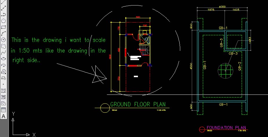
Good day.. I"m having a hard time in get the correct scale.. or to scale the drawing from 1:100 mts to 1:50 mts. Comparing the two drawing, 1:50 is much larger than 1:100 mts. I tried to scale my drawing which is in 1:100 with the reference scale factor "2" and i compare it to the 1:50 dwg but it did match...TIA I hope you can help me guys.. thanks a lot. ------------- Thanks.. AKOARKITEKTO |
Replies:
Posted By: John Connor
Date Posted: 15.Apr.2015 at 12:24
|
Please confirm you are in a paper space layout using at least one viewport. Yes/No/Not sure? ------------- "Humans have a strength that cannot be measured. This is John Connor. If you are reading this, you are the resistance." <<AutoCAD 2015>> |
Posted By: akoarkitekto
Date Posted: 16.Apr.2015 at 02:46
|
no i am working in "model" and i have a 20"x30" template or A1 size paper.. In "layout" i paste the template and put one viewport and zoom it with 1/5xp and drawing is still small... ------------- Thanks.. AKOARKITEKTO |
Posted By: akoarkitekto
Date Posted: 16.Apr.2015 at 02:55
------------- Thanks.. AKOARKITEKTO |
Posted By: akoarkitekto
Date Posted: 16.Apr.2015 at 03:35
|
.......or just it the secret is in dimstyle? or dimscale?... ------------- Thanks.. AKOARKITEKTO |
Posted By: John Connor
Date Posted: 16.Apr.2015 at 11:53
|
It sounds like you have a mixed units problem. You reference a scale factor of 1:50 (metric) yet your paper size is stated in imperial units (20"x30"). Never a good idea to mix metric and imperial. Attach a copy of the drawing to your next post or upload it to the CAD Blocks section of this website. Images aren't useful at this point; we need a DWG file. ------------- "Humans have a strength that cannot be measured. This is John Connor. If you are reading this, you are the resistance." <<AutoCAD 2015>> |
Posted By: akoarkitekto
Date Posted: 16.Apr.2015 at 12:13
|
Please see attached file.. this is the sample cad file that i am working with.. 1.Another question is.. the elevation in the drawing said that is scaled in 1:50mts. But when i draw a line with the same measurement like 5.000 mts and compare it with the drawing.. it's the same but when i measured its dimension it gives me the wrong dimension.. 2. How can i scale the elevation into 1:20 mts like in section details... or is that i draw it first in 1:100 mts and then just scale/resize it bigger to <scale><reference>2.? Thanks. CAD FILE: uploads/552290/FOR_CAD_FORUM.dwg" rel="nofollow - uploads/552290/FOR_CAD_FORUM.dwg
------------- Thanks.. AKOARKITEKTO |
Posted By: philippe JOSEPH
Date Posted: 16.Apr.2015 at 13:09
|
http://www.cadforum.cz/forum_en/uploads/175428/FOR_CAD_FORUMPJH.dwg" rel="nofollow - uploads/175428/FOR_CAD_FORUMPJH.dwg
Hello akoarkitekto, you have mainly 2 problems on your file :
The drawing on the right has beem scaled by 2.5 and the dimension style STANDARD$0 for linear dimensions has been modified with a scale factor of 0.4 to cope this ( x2.5 = 0.4).
It's better to work at scale 1/1 and open viewports in the paper space to have different paper scales.
The drawing on the left is OK ( drawn in meters , dimension style STANDARD$0 is working ).
You can work with different units in different files or insert ( and not copy/paste ) different units files inside the first one but you have to set UNITS with the good value in the diffrent files. |
Posted By: akoarkitekto
Date Posted: 17.Apr.2015 at 03:16
|
thanks for the help guys. but how can i insert the the scaled drawing from the layout to model? or insert different cad file on the on my working area.? sorry for my questions, im just new in this matter. about scaling
------------- Thanks.. AKOARKITEKTO |
Posted By: philippe JOSEPH
Date Posted: 17.Apr.2015 at 07:42
|
Hello Akoarkitekto, I think that you will have to learn about viewports in the layout space ( paper space ).
In AutoCAD or you work in the model space ( and you have to "scale" things to have different scales in the same drawing ) or you work at scale 1/1 in the model space and open viewports in the layout(s) at different zooms ( scale ) to set different scales on the same drawing.
Have you open the file that I have uploaded : FOR_CAD_FOROMPJH.dwg and took at look at it ?
The concept of view ports is maybe difficult in the beginning but after it offers much security ( no scaled drawings ).
The model space is the workshop and the layout space is the screen of your computer in the office.
You should ask for this to your teachers, friends or colleagues at work.
You should find lessons on the internet about this, maybe in CADTUTORIAL or AUTODESK COMUNNITY or...
Launch a search with : autocad viewports.
Take alook at this : https://www.andrew.cmu.edu/course/48-568/PDFs/AutoCAD2D/Chapter28.pdf" rel="nofollow - https://www.andrew.cmu.edu/course/48-568/PDFs/AutoCAD2D/Chapter28.pdf
Ask for more and have a good day.
|
Posted By: akoarkitekto
Date Posted: 17.Apr.2015 at 12:08
|
Hello philippe joseph thanks for your help. i've just review your uploaded cad file and i've noticed that in the elevation section you changed the scale note from 1:50 - 1:40.. but i think it's in the scale of 1:10 and in the layout part can i ask if what zooming scale did you use.: <zoom><scale>40xp? for the elevation? and <zoom><scale>50xp? for the section? thanks.... ------------- Thanks.. AKOARKITEKTO |
Posted By: John Connor
Date Posted: 17.Apr.2015 at 12:45
|
I looked at the drawing that Philippe uploaded and it appears to me that he only used two scales. The viewport on the left has a scale of 1:25 and the one on the right has a scale of 1:50. I don't know where you are getting a scale of 1:10. The one main thing you need to keep in mind is that all objects in model space should be drawn FULL size. If a building is 15 meters wide that's what you draw it. You do NOT scale a drawing as you would if you were doing it on a piece of paper using manual drafting methods. Once your drawing is completed then you switch to a layout and start creating Viewports. Viewports are merely windows that allow us to see the objects we created back in model space. Viewports are assigned a scale NOT the objects back in model space. When it comes time to print you do so at a scale of 1:1. AutoCAD will automatically take care of scaling the various viewports based on the scale assigned to them. It appears that your drawing was done using a method that mimics exactly what one would do if manually drafting the drawing on a drafting board. That is the wrong approach. Why? Because you run into the exact problem you described. Example: the height of your house. On the two elevation views it measures 5.00 yet in the sectional view it measures 12.5 (2.5 times larger). I'd suggest you do some reading and view some tutorials about using paper space layouts and viewports and how to properly set up a drawing that utilizes these features. ------------- "Humans have a strength that cannot be measured. This is John Connor. If you are reading this, you are the resistance." <<AutoCAD 2015>> |
Posted By: John Connor
Date Posted: 17.Apr.2015 at 12:53
|
I just noticed one other thing with your drawing. Although you appear to want to draw using metric units your template file turns out to be one that uses imperial units (decimal inches) rather than metric units. In the future you should use a metric template file every time you start a new drawing. One such template that comes standard with AutoCAD is acadiso.dwt. Another metric template is named Tutorial-mArch.dwt (for metric architectural drawings). Do NOT use the default template file named acad.dwt because it uses imperial units. Understand? ------------- "Humans have a strength that cannot be measured. This is John Connor. If you are reading this, you are the resistance." <<AutoCAD 2015>> |
Posted By: philippe JOSEPH
Date Posted: 17.Apr.2015 at 13:30
|
Hello again akoarkitekto, in fact I haven't focused on the dimensions apearances ( mainly the height of the texts and the dimensions of the arrows ) but I have set correctly the scale of the 2 viewports on a A1 paper size.
There are many ways to set the dimensions and this should be done with a "prototype file" of your own or of your company.
The most important here is to learn viewports and scales to drawn at scale 1/1 in the model space.
|
Posted By: John Connor
Date Posted: 17.Apr.2015 at 13:34
|
By "prototype" I think Philippe is suggesting that you consider creating a custom template file that has all your layers, linetypes, text styles, dimension styles, title block and border, etc. already included so that every time you start a new drawing you do not have to recreate all of these items from scratch. Many companies follow this method and create custom template files for different size drawings. BTW...when using layouts it is customary to place one's title block and border in the layout and not in model space. As for dimensions and text you have a couple of options. They can be placed in model space using annotative scaling or they can be placed in your layout. Each method has its pros and cons and should be tried/tested before deciding which method works best for your particular situation. There is no "right" or "wrong" way there are just multiple ways. ------------- "Humans have a strength that cannot be measured. This is John Connor. If you are reading this, you are the resistance." <<AutoCAD 2015>> |
Posted By: akoarkitekto
Date Posted: 18.Apr.2015 at 06:11
|
thanks guys for all your suggestions and comments. I've learned a lot from that.. thanks also for cadforum :) ------------- Thanks.. AKOARKITEKTO |
Posted By: sajjad137
Date Posted: 29.Apr.2015 at 06:21
|
Hello....hope u all will be fine.....brother i am facing a problem....when i convert a file from Contours Shapefile for a large area to CAD file then its size is increased so much that it becomes difficult to handle it in CAD, also the the vertices on the lines are very much....plz telly me the solution anybody.............. ------------- Sajjad |
Posted By: John Connor
Date Posted: 29.Apr.2015 at 11:35
|
You do realize you are hijacking a thread started by someone else about an entirely different subject don't you? That is considered bad form. What program are you using? It does not sound like plain AutoCAD. ------------- "Humans have a strength that cannot be measured. This is John Connor. If you are reading this, you are the resistance." <<AutoCAD 2015>> |