Automatic design based on variables
Printed From: CAD Forum
Category: EN
Forum Name: AutoCAD
Forum Description: Discussion about AutoCAD and AutoCAD LT, viewers, DWG and DXF formats, Design Review, AutoCAD web, Drive, add-ons
URL: https://www.cadforum.cz/forum_en/forum_posts.asp?TID=11934
Printed Date: 20.Oct.2026 at 19:07
Topic: Automatic design based on variables
Posted By: alexjahrens
Subject: Automatic design based on variables
Date Posted: 26.Jul.2016 at 23:42
|
Hi all, Not sure if this can be done in AutoCad, or if anyone knows of some other software that would allow for this. I have a design "standard" that I need to customize based on customer requirements, and need to do this many times a day, so would like to semi-automate this. Here's the standard design: 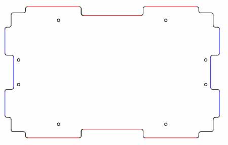 Basically, I need this shape to fit inside overall customer dimensions of Length and Width. To do this, I add or subtract length to the red and blue lines only - I don't touch the black lines. For example, say the above "standard" design fits in a box that's 20" x 12". My customer's box is 26" x 15". To make this custom design, I add 2" to each of the red lines and 1" to each of the blue lines. Ideally, I would be able to run a "program" where it asks me for Length and Width, I type in L=26 and W=15, and it automatically adjusts the design. Anyone know how to go about doing this? It seems like it should be kinda simple, if there was a way to take a design, select components of it, and assign variables to them.
|
Replies:
Posted By: rebellio
Date Posted: 27.Jul.2016 at 13:37
|
Hi, It can be don for sure in acad using VBA or Lisp programming. But why not use Wblocks? As far as i understand you created already a lot of those plates....... regards Ron
|
Posted By: John Connor
Date Posted: 27.Jul.2016 at 14:13
|
And how exactly would a regular block work in this case? The change in length is being applied to specific lines not to the overall length or width. Might be better off with a dynamic block that covers the range of smallest to largest plates using suitable increments. ------------- "Humans have a strength that cannot be measured. This is John Connor. If you are reading this, you are the resistance." <<AutoCAD 2015>> |
Posted By: rebellio
Date Posted: 27.Jul.2016 at 17:23
|
Hi,Depends on the variety of boxes thats needed a asume that those boxes will have a standard dimension.If it is like that you can do a lott with Wblocks, IF not Scripting/VBA or Lisp will be the best to go for. Regards Ron
|
Posted By: John Connor
Date Posted: 27.Jul.2016 at 17:38
|
Please demonstrate your wblock suggestion using the example the OP cited keeping in mind you can only change the lengths of the three red and the three blue lines. Explain how you accomplished the task step-by-step so the viewers at home can replicate your success. ------------- "Humans have a strength that cannot be measured. This is John Connor. If you are reading this, you are the resistance." <<AutoCAD 2015>> |
Posted By: John Connor
Date Posted: 27.Jul.2016 at 18:03
|
alex: Is there a minimum and maximum size? Normally when a plate is resized is it done is full inches or fractions of inches? For example might the plate go from 20x12 to 22x14.5? In other words, are oddball sizes commonly required? My only reason for asking is in regards to the possible use of a dynamic block. ------------- "Humans have a strength that cannot be measured. This is John Connor. If you are reading this, you are the resistance." <<AutoCAD 2015>> |
Posted By: alexjahrens
Date Posted: 27.Jul.2016 at 19:00
|
Oddball sizes aren't common - typically the outside dimensions end on the inch. Sizes range from a minimum of about 12" to a maximum of 72" or so. Thanks for the help, everyone - I'm not familiar with dynamic blocks, but I'm reading up on them!
|
Posted By: John Connor
Date Posted: 27.Jul.2016 at 19:13
|
Any progress yet rebellio? Anxious to see what you have come up with. ------------- "Humans have a strength that cannot be measured. This is John Connor. If you are reading this, you are the resistance." <<AutoCAD 2015>> |
Posted By: rebellio
Date Posted: 28.Jul.2016 at 09:46
|
Hi, What i mean by Using Wblocks is that you create a library on the job and drag and drop them in a new Toolpallet so you can use them later. In this way you only have to select de correct size and directly insert them in the drawing. FoR Example 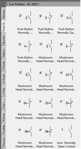 I think with dynamics blocks it is still to much manual handling. Most idealy is create a lisp or vba with calculation function so that you only have to give 2 or 3 WxHxD dimensions. @ Alex can you post a copy of that standard design (dwg) ? Than i can see what i can do, I can not promise you anything because im not a lisp expert regards Ron
|
Posted By: John Connor
Date Posted: 28.Jul.2016 at 11:25
|
So in other words your WBlock idea is to create a block for each and every different size and put it on a tool pallet? That's it? Really?? ------------- "Humans have a strength that cannot be measured. This is John Connor. If you are reading this, you are the resistance." <<AutoCAD 2015>> |
Posted By: rebellio
Date Posted: 28.Jul.2016 at 12:58
|
Hi, Thats one of the options indeed, at the end you will always be faster than using dynamic blocks because of the extra manual handling. Just for your info all Database structured programs are using libraries so why not create one for this issue. So dont act funny my friend. Again BEST IS VBA OR LISP Regards Ron
|
Posted By: John Connor
Date Posted: 28.Jul.2016 at 13:27
|
I wasn't going for funny. I was going for incredulous. I thought you had some whiz-bang idea but it turns out you didn't. If the OP changes sizes often enough then his company would be better off hiring a lisp guru to create a custom program. ------------- "Humans have a strength that cannot be measured. This is John Connor. If you are reading this, you are the resistance." <<AutoCAD 2015>> |
Posted By: rebellio
Date Posted: 28.Jul.2016 at 13:33
I Just provide a solution not the solution 
|
Posted By: alexjahrens
Date Posted: 28.Jul.2016 at 17:39
|
Ron, attached is the file. Thanks for the feedback everyone. |
Posted By: John Connor
Date Posted: 28.Jul.2016 at 18:19
|
Now give him a list of some of the sizes that are required. Maybe Ron will create most of your blocks for you. He seems willing. ------------- "Humans have a strength that cannot be measured. This is John Connor. If you are reading this, you are the resistance." <<AutoCAD 2015>> |
Posted By: rebellio
Date Posted: 29.Jul.2016 at 09:24
cant you not just travel back in time or something John connor? eikel 
|
Posted By: rebellio
Date Posted: 29.Jul.2016 at 09:26
| Thanks alex i will see what i can do |
Posted By: John Connor
Date Posted: 29.Jul.2016 at 11:53
|
Be careful what you wish for. I know where your mother lives. Hey! You were the one that came up with the idea so consider it a challenge. You asked for it....now show us your stuff. When can we expect the first twelve blocks? ------------- "Humans have a strength that cannot be measured. This is John Connor. If you are reading this, you are the resistance." <<AutoCAD 2015>> |
Posted By: John Connor
Date Posted: 31.Jul.2016 at 15:15
|
No blocks yet? Did you go on holiday? LoL ------------- "Humans have a strength that cannot be measured. This is John Connor. If you are reading this, you are the resistance." <<AutoCAD 2015>> |
Posted By: Kent Cooper
Date Posted: 01.Aug.2016 at 20:22
That should be able to be automated, but (whether you're going for something like an AutoLisp routine or a dynamic Block) questions arise. For instance, in this image, should the C dimensions remain constant (as seems likely to me), or should they be affected by changes in outside dimensions? Should the A dimensions remain constant, or should the ratio between the A's and the B's be the constant, or is there some other criterion for positioning the holes (if that's what those circles are) in that direction? Should the hole diameters remain constant? 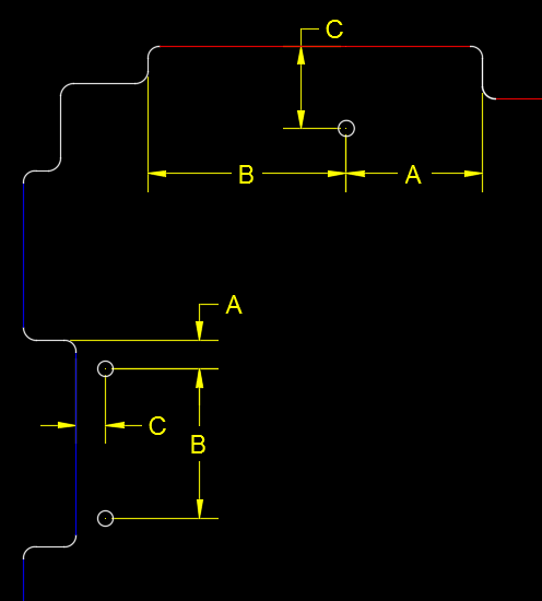 Since the inner red and blue lines are not the same lengths as the outer ones, should the lengths of those lines be adjusted equally as overall dimensions change, or proportionally? That is, if you need a layout that's 3" shorter in the red-lines direction, should each red line be made 1" shorter, or should the longer middle one have more removed from it than the shorter end ones, so that the ratio of their lengths remains the same? Since the inner red and blue lines are not the same lengths as the outer ones, should the lengths of those lines be adjusted equally as overall dimensions change, or proportionally? That is, if you need a layout that's 3" shorter in the red-lines direction, should each red line be made 1" shorter, or should the longer middle one have more removed from it than the shorter end ones, so that the ratio of their lengths remains the same?
|
 alexjahrens wrote:
Posted By: John Connor
Date Posted: 02.Aug.2016 at 13:18
|
Kent Cooper has brought up some very valid points. Can we get some response? ------------- "Humans have a strength that cannot be measured. This is John Connor. If you are reading this, you are the resistance." <<AutoCAD 2015>> |
Posted By: rebellio
Date Posted: 11.Aug.2016 at 17:19
|
Hi Alex, Found some time to write something for you. Please use the standard drawing that you posted (or the Panel_Inch attached), the lisp is based on that drawing. The Lisp i wrote will "stretch" the lenght and width. If Gap is required open the lisp (notepad) and check this rule "If Gap required set Lgap 0.00 to 0.05 or Up" Load the lisp with Appload and type STRPLA on the command bar to Run. Hope that this will help you. Regards uploads/39979/panel_INCH.dwg" rel="nofollow - uploads/39979/panel_INCH.dwg uploads/39979/Stretchplate.LSP" rel="nofollow - uploads/39979/Stretchplate.LSP ps i am used to the metric system
 and decimal settings. and decimal settings. |