What Kind of Projection Is This?
Printed From: CAD Forum
Category: EN
Forum Name: AutoCAD
Forum Description: Discussion about AutoCAD and AutoCAD LT, viewers, DWG and DXF formats, Design Review, AutoCAD web, Drive, add-ons
URL: https://www.cadforum.cz/forum_en/forum_posts.asp?TID=13307
Printed Date: 05.Sep.2026 at 02:23
Topic: What Kind of Projection Is This?
Posted By: dery
Subject: What Kind of Projection Is This?
Date Posted: 17.Oct.2019 at 21:29
|
Can someone please tell me what kind of projection (for example: isometric, dimetric, etc.) is this? (Please see below image for more detail) Thank you 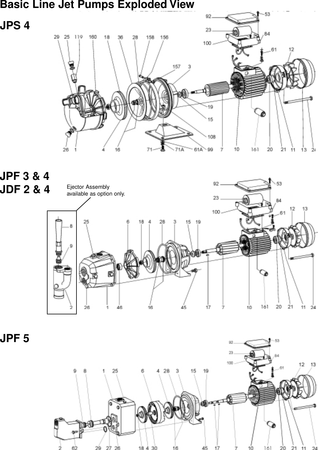 |
Replies:
Posted By: philippe JOSEPH
Date Posted: 18.Oct.2019 at 08:52
|
Hello dery, I think it's a 3D point of view based on an isometric view modified so that to see better the different elements. If you do some 3D work, take a "standard" isometric point of view then modify it to see better the object(s). Launch the command DDVPOINT and see the angle : relative to UCS If the object is tall then lower the "vertical" ( relative to UCS ) angle to see "inside" your object, 35.3° modified to 25° for example. If the object is flat then increase the "vertical" ( relative to UCS ) angle to see "on top" of your object, 35.3° modified to 45° for example. 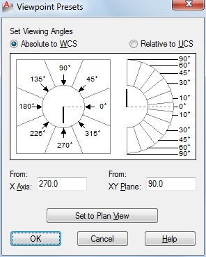 |
Posted By: John Connor
Date Posted: 18.Oct.2019 at 17:18
|
I believe it could very well be a 2D isometric view using dimetric projection. ------------- "Humans have a strength that cannot be measured. This is John Connor. If you are reading this, you are the resistance." <<AutoCAD 2015>> |
Posted By: philippe JOSEPH
Date Posted: 18.Oct.2019 at 17:58
|
OK John and dery but I don't see equal the 2 angles "A" and "C". If it's a 3D point of view 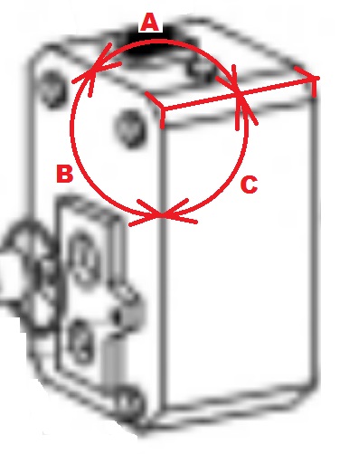 on a 3D object, how can we set the DDVIEWPOINT angles to have a good dimetric view ? |
Posted By: philippe JOSEPH
Date Posted: 18.Oct.2019 at 18:10
| In fact The angle "A" is greater than the angle "C" and you can check it for example by redrawing an object with a paper on your screen and measuring the angles or rotating that paper for a check on the other angle. |
Posted By: philippe JOSEPH
Date Posted: 18.Oct.2019 at 20:17
| Valid for everybody : See the related CAD tip N° 4793: https://www.cadforum.cz/cadforum_en/qaID.asp?tip=4793" rel="nofollow - Dimetry - dimetric projection of AutoCAD 3D objects. |
Posted By: dery
Date Posted: 18.Oct.2019 at 20:38
That's why ask the question because it does not look like an isometric projection to me.
|
 philippe JOSEPH wrote:
Posted By: dery
Date Posted: 18.Oct.2019 at 20:41
What do you mean by "2D isometric view using dimetric projection"? I don't understand. Do you mean the projection is combined? Clearly it can be seen that the drawing is not isometric projection.
|
Posted By: philippe JOSEPH
Date Posted: 18.Oct.2019 at 22:39
|
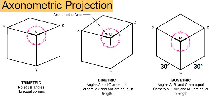
Dery, if you do a search on the internet you will find the various projections : isometric, dimetric with their diffrerent settings on the angles and length ( dimetric = 2 angles and length are equal, isometric = 3 angles and length are equal ). The drawings are not isometric and not dimetric but from a 3D point of view ( isometric modified to see better the elements ).
Is your work 2D or 3D, I hope it's 3D because is now less work than the old way to draw.
 |
Posted By: philippe JOSEPH
Date Posted: 19.Oct.2019 at 08:08
| And the answer is : ........................................................................ TRIMETRIC........................................................... |
Posted By: John Connor
Date Posted: 19.Oct.2019 at 14:59
|
I never though the drawing was 3D. Always looked 2D to me. ------------- "Humans have a strength that cannot be measured. This is John Connor. If you are reading this, you are the resistance." <<AutoCAD 2015>> |
Posted By: philippe JOSEPH
Date Posted: 19.Oct.2019 at 18:35
|
Yes John the "drawing" is 2D but I hope that the informatic work was done in 3D and not with the "like on the drawing board old way". I have never really done 2D isometric drawing or only for scheme or pipings with symbols but now with the "real" 3D we can do all this better and quicker. The level of detail shown on the drawings makes me think that it's real 3D. Eventually see my AutoCAD file : https://www.cadforum.cz/catalog_en/block.asp?blk=11163" rel="nofollow - ORTHO-TO-ISO_01_B .dwgin the CAD/BIM Blocks library done in answer of a cad discussion. I had realized a 2D isometric drawing from an image file by doing real 3D solids and then FLATSHOT it.
|