What Drawing This Is?
Printed From: CAD Forum
Category: EN
Forum Name: AutoCAD
Forum Description: Discussion about AutoCAD and AutoCAD LT, viewers, DWG and DXF formats, Design Review, AutoCAD web, Drive, add-ons
URL: https://www.cadforum.cz/forum_en/forum_posts.asp?TID=14778
Printed Date: 22.Jun.2026 at 14:29
Topic: What Drawing This Is?
Posted By: teknol
Subject: What Drawing This Is?
Date Posted: 01.May.2026 at 18:45
Can anyone tell me please what drawing is this, what it's used for, and how to make and use it in Autocad? Thanks.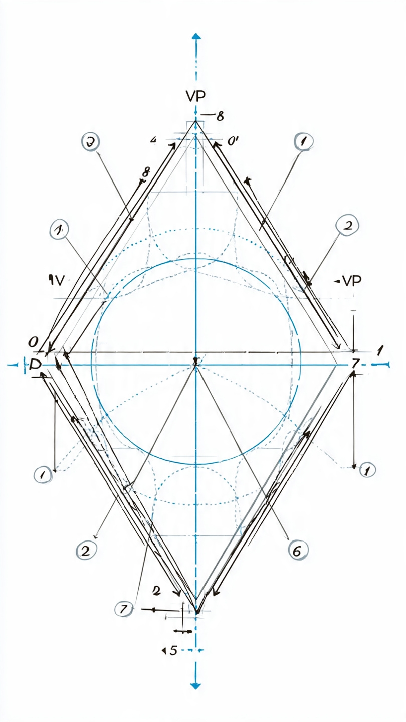
|
Replies:
Posted By: philippe JOSEPH
Date Posted: 05.May.2026 at 07:06
|
Hello teknol, were did you find this drawing ? This drawing doesn't include the necessary dimensions to draw it on AutoCAD.
|
Posted By: simutecra
Date Posted: 05.May.2026 at 09:54
This is a geometric construction / engineering drawing, specifically it looks like a descriptive geometry layout used to define relationships between shapes (likely a circle inside a rotated square/diamond with projection lines). You’ll often see this in:
What it’s used forIt’s mainly used to:
How to make it in AutoCADYou don’t draw this as a single command, it’s built step by step:
How it’s “used” in practiceIn real CAD work, this type of drawing is more of a planning/understanding tool rather than something you deliver. Once you understand the geometry, you’d typically:
------------- Simutecra |