Hole Dimension
Printed From: CAD Forum
Category: EN
Forum Name: CAD - general
Forum Description: General discussion about CAD, formats, standards, management, licensing, networking, harware, other CAD applications
URL: https://www.cadforum.cz/forum_en/forum_posts.asp?TID=9131
Printed Date: 10.Jun.2026 at 15:21
Topic: Hole Dimension
Posted By: kenjg
Subject: Hole Dimension
Date Posted: 11.Apr.2013 at 22:20
|
Hello All, I have a general question. I have a PDF file I'm re-drawing into CAD form and I show a HOLE with the following dims 1.98 H7. The H7 is upward of the dim, not right next to it. I think it reads a + something and - 0.000 I read that the H7 is a tolerance of 0.0025mm. I've attached the drawing to get my meaning. I had the part made using this dim and the part (2mm Dowel Pin) slides easily in the hole. I measured th Pins and they are all 2mm. Thanks in Advance. KenJG 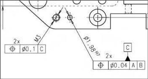 |
Replies:
Posted By: philippe JOSEPH
Date Posted: 12.Apr.2013 at 07:26
|
Hello Kenjg, please find here some explanations about the tolerances.
H7 is +0 , +...
For a diameter of 1.98 mm it will be +0 , +0.010 mm.
For your diameter of 1.98 that gives :
1.98 + 0 = 1.98 minimum
1.98 + 0.010 = 1.99 maximum.
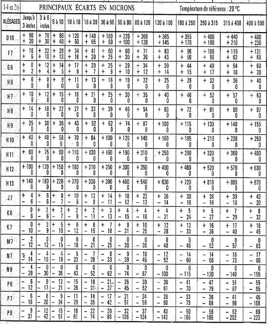
If you do a search in Wikipedia you will find informations but it will talk about the fundamental tolerances IT + the values that you have to had to it etc... Prefer finding some complete tables like the one here under.
Ask for more
 |
Posted By: philippe JOSEPH
Date Posted: 12.Apr.2013 at 21:32
|
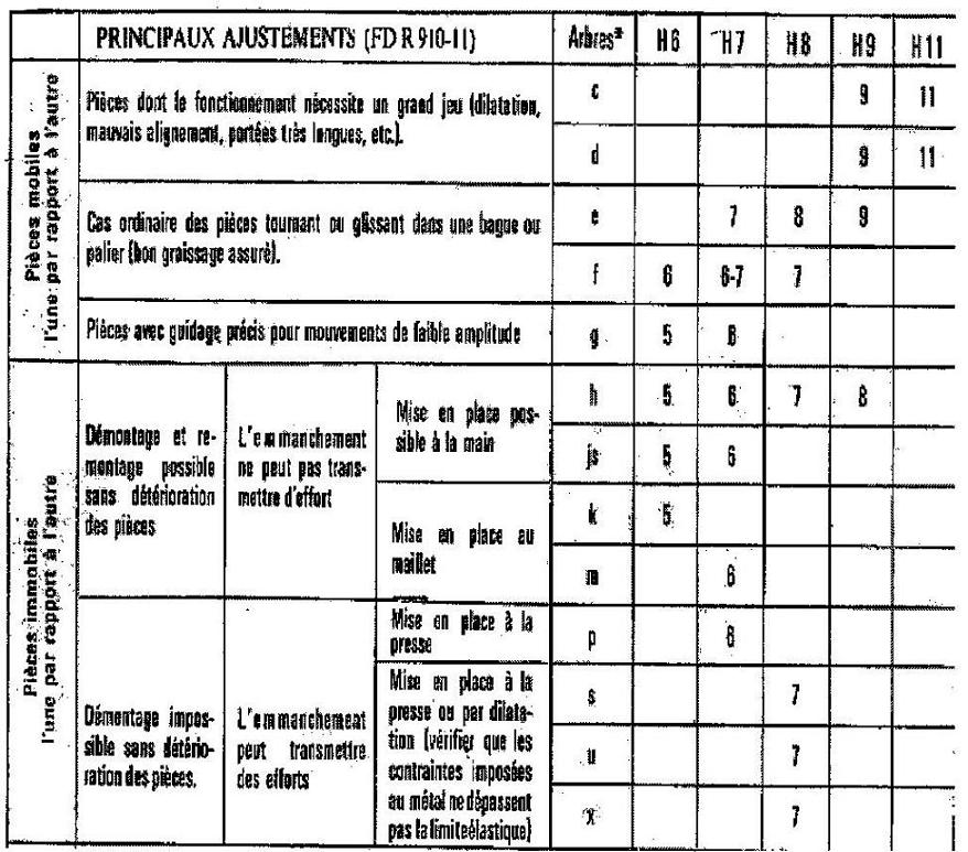
If it’s too complicated use the “H7 hole system” that is the most used and is based on the normalisation of the dimensions of holes to the tolerance H7 ( holes are much more difficult to machine than shafts ) + shafts to be mounted inside with different tolerances from e7 ( sliding ) to p6 ( assembly with press or thermal expansion ). Small letters are for shafts and capital letters are for holes. 6 is a very precise work, 7 is medium, 11 is a rough work. principaux ajustements
main fittings pieces dont le fonctionnement necessite un grand jeu parts that needa big clearance dilatation, mauvais alignement, portees tres longues
expansion, bad alignment, very long bearings cas ordinaire des pieces tournant ou glissant dans une bague ordinary case of parts sliding in bushing bon graissage assuré good lubrication guaranteed pieces avec guidage precis pour mouvement de faible amplitude parts with good guidance for low amplitude movements démontage et remontage possible sans deterioration des pieces dismantling and reassembly possible without wear of the parts démontage impossible sans deterioration des pieces dismantling and reassembly impossible without wear of the parts the fitting cannot transmit force the fitting can transmit force mise en place possible a la main assembly possible by hand assembly with rubber hammer mise en place a la presse assembly with press mise en place a la presse ou par dilatation assembly with press or with thermal expansion |
 Hello Kenjg, I’m coming back on your question about tolerances and you will find a table explaining the main fittings.
Posted By: kenjg
Date Posted: 13.Apr.2013 at 16:28
|
Hello Philippe, Thank you SOO much. I didn't know the dims where in MICRONS. Take care and I'll be back another day. Best Regards KenJG
|
Posted By: philippe JOSEPH
Date Posted: 15.Apr.2013 at 12:16
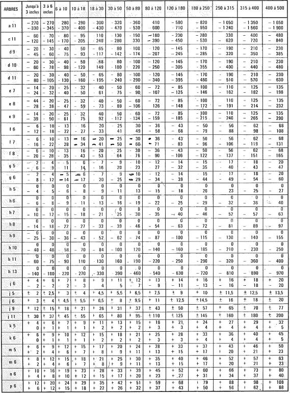
Hello N° 3 Kenjg, this is the table that you should read to adjust the tolerance of your pin to have it stucked in the hole ( or not ).
The table with small letters are for shafts, the table with capital letters are for holes.
Use the system H7 ( hole ) m6 ( pin ) if you want it fixed.
Use an other system for an other fitting ( sliding , etc... )
|