Drawing Splines with blocks
Printed From: CAD Forum
Category: EN
Forum Name: CAD - general
Forum Description: General discussion about CAD, formats, standards, management, licensing, networking, harware, other CAD applications
URL: https://www.cadforum.cz/forum_en/forum_posts.asp?TID=9772
Printed Date: 28.Sep.2026 at 21:09
Topic: Drawing Splines with blocks
Posted By: robertzeis
Subject: Drawing Splines with blocks
Date Posted: 01.Nov.2013 at 13:29
|
I am looking for the best way to draw freeform and straight bands of brick for my landscape plans. I end up drawing a spline then offsetting it by length of given brick size and then freehand drawing lines for the joints. I know there must be an easy way to do this. THanks
------------- bob zeis |
Replies:
Posted By: John Connor
Date Posted: 01.Nov.2013 at 13:45
|
Have you tried using hatch patterns? ------------- "Humans have a strength that cannot be measured. This is John Connor. If you are reading this, you are the resistance." <<AutoCAD 2015>> |
Posted By: robertzeis
Date Posted: 01.Nov.2013 at 14:56
|
Hatch pattern wont work for single side by side brick bands. especially if I need the brick to be laid along a curved line. ------------- bob zeis |
Posted By: John Connor
Date Posted: 01.Nov.2013 at 15:02
|
If you used a custom lisp routine that curved the brick it would. Do you draw the joints as well? Can you post an image of something you've done? ------------- "Humans have a strength that cannot be measured. This is John Connor. If you are reading this, you are the resistance." <<AutoCAD 2015>> |
Posted By: robertzeis
Date Posted: 01.Nov.2013 at 15:12
|
Typically I just draw a line between. I plot plans in 1/8" scale so it doesnt need that much detail. I have never use lisp routines although I have read about them a lot. ------------- bob zeis |
Posted By: robertzeis
Date Posted: 01.Nov.2013 at 15:12
|
Problem is I work alone in my home office, so I dont have anyone to show me how they work. ------------- bob zeis |
Posted By: John Connor
Date Posted: 01.Nov.2013 at 15:18
|
Lisp routines can be loaded in a couple of different ways. One option is to use the APPLOAD command. AutoCAD prompts you for the lisp file location, you browse to it, highlight it then click on the Load button. AutoCAD will tell you if it was successfully loaded or not. Depending on how the lisp routine was written you may or may not be told what to type at the command line to invoke the command. If everything goes OK you just type what is shown, the command starts and you follow the prompts. Fairly straightforward. What size brick(s) do you normally spec? Is the drawing used strictly for presentation purposes or do you also use it to calculate quantities of materials (i.e. - the number of bricks required for the walkway)? ------------- "Humans have a strength that cannot be measured. This is John Connor. If you are reading this, you are the resistance." <<AutoCAD 2015>> |
Posted By: robertzeis
Date Posted: 01.Nov.2013 at 15:43
|
It is for presentation, I use properties to get area measurements. Typical Brick sizes are 5"x8" and 4"x8" ------------- bob zeis |
Posted By: John Connor
Date Posted: 01.Nov.2013 at 15:45
|
Can you post an image of one of your curved sidewalk layouts? A closeup would suffice. Maybe an area equal to 4'x8'? ------------- "Humans have a strength that cannot be measured. This is John Connor. If you are reading this, you are the resistance." <<AutoCAD 2015>> |
Posted By: John Connor
Date Posted: 01.Nov.2013 at 16:00
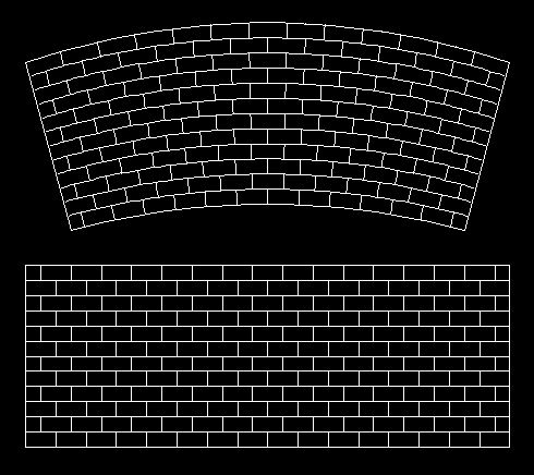 I am using generic AutoCAD 2013. The hatch pattern is BRICK. The bottom part of the image is typical of what AutoCAD can do in a normal square/rectangular area. The top part of the image is the same hatch pattern after being applied to a curved area using a custom lisp routine. ------------- "Humans have a strength that cannot be measured. This is John Connor. If you are reading this, you are the resistance." <<AutoCAD 2015>> |
Posted By: John Connor
Date Posted: 01.Nov.2013 at 16:13
|
I've had a chance to play around with this custom lisp routine and I kind of have a sense of how it works. I think it could be quite useful but it could be a matter of trial-n-error to end up with the desired affect one is trying to achieve. ------------- "Humans have a strength that cannot be measured. This is John Connor. If you are reading this, you are the resistance." <<AutoCAD 2015>> |
Posted By: robertzeis
Date Posted: 01.Nov.2013 at 16:30
|
Hi John, The field of brick or pavers would remain in straight line. The Border is what I need to populate with side by side brick along a curved line. ------------- bob zeis |
Posted By: John Connor
Date Posted: 01.Nov.2013 at 16:37
|
AutoCAD 2010? Does that have a path array option? If so then it might work for the border. In the field of brick or pavers remain in a straight line I suppose you could hatch an area larger than your walkway, drop your walkway over it, explode the hatch and Extrim everything outside the edge of walk. Exploding hatch patterns is not usually recommended though because it can balloon a drawing's file size but I suppose that would depend on how much hatching was involved. ------------- "Humans have a strength that cannot be measured. This is John Connor. If you are reading this, you are the resistance." <<AutoCAD 2015>> |
Posted By: John Connor
Date Posted: 01.Nov.2013 at 16:49
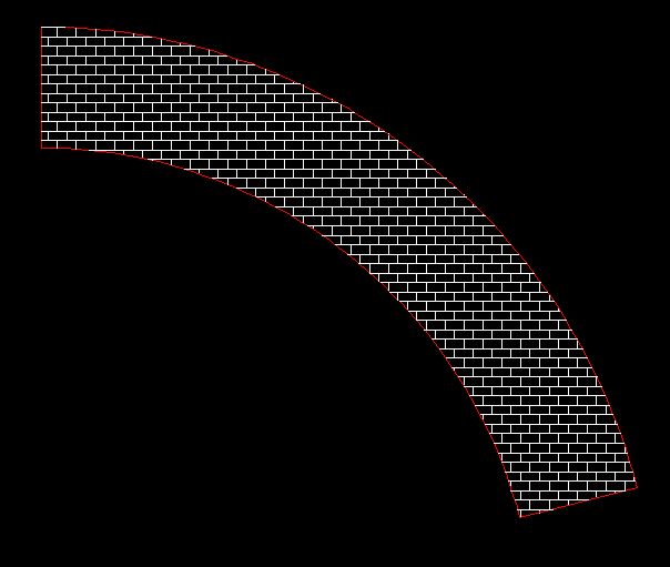 Forget the border for a moment. Is this how you run the brick around a curve? ------------- "Humans have a strength that cannot be measured. This is John Connor. If you are reading this, you are the resistance." <<AutoCAD 2015>> |
Posted By: robertzeis
Date Posted: 02.Nov.2013 at 19:15
|
Yes the pattern remains straight, not curved ------------- bob zeis |
Posted By: John Connor
Date Posted: 02.Nov.2013 at 21:58
|
Well I did that using the method I described previously. Which as involved as it is would probably be faster than your method. You never told me if 2010 had the path array option. Does it? ------------- "Humans have a strength that cannot be measured. This is John Connor. If you are reading this, you are the resistance." <<AutoCAD 2015>> |
Posted By: robertzeis
Date Posted: 02.Nov.2013 at 22:08
|
Yes it has array option. Im confused on how it is used. ------------- bob zeis |
Posted By: John Connor
Date Posted: 03.Nov.2013 at 12:04
|
I know it has an array option but I'm not talking about a polar or a rectangular array. At some point AutoDesk added a "path" option where the user could array objects along a path (like a centerline for instance). Nevermind. I'll find the answer myself and post it back here when I do. ------------- "Humans have a strength that cannot be measured. This is John Connor. If you are reading this, you are the resistance." <<AutoCAD 2015>> |
Posted By: John Connor
Date Posted: 03.Nov.2013 at 13:22
|
I'm almost 100% positive the "path array" was added in 2012 not 2010. However, you have a couple of other option and they are DIVIDE and MEASURE. Each can be used with a block which would make creating your border of bricks (not the pathway itself) easier. ------------- "Humans have a strength that cannot be measured. This is John Connor. If you are reading this, you are the resistance." <<AutoCAD 2015>> |
Posted By: Kent Cooper
Date Posted: 04.Nov.2013 at 22:51
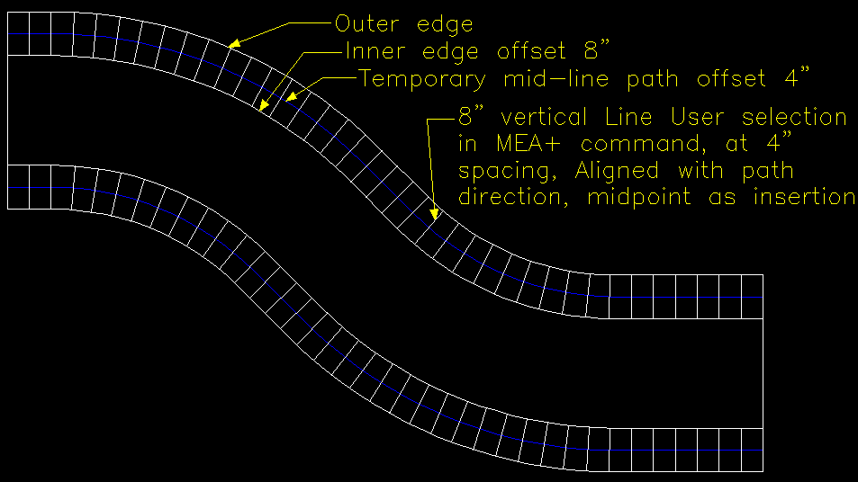
Check this out:
http://cadtips.cadalyst.com/2d-operations/divide-and-measure-plus" rel="nofollow - http://cadtips.cadalyst.com/2d-operations/divide-and-measure-plus
You can use the MEA+ command in that to establish your curved edges. I would recommend offsetting a temporary center-line-of-the-bricks-along-the-edge route, and using either a rectangular Block defined with its midpoint as the insertion, or if you don't want the double lines at the joints at small scale (see image), you can use just a Line with its midpoint as the reference location for placing them along the route. Unlike regular Measure, MEA+ lets you place a User selection [the Line if that's what you choose] in addition to the Points and Blocks options, and lets you specify any angle Relative to the route, not just 0 or Aligned, so if you use a Block orthogonally defined, you would presumably use it at 0 or 90 degrees relative to the route, depending on how the Block's definition is oriented and whether you want a soldier-course or running-course edge. MEA+ and its companion DIV+ command also have many other enhancements over ordinary Measure and Divide.
|
Posted By: robertzeis
Date Posted: 04.Nov.2013 at 22:55
|
Thanks, i will give that a look and see if I can do that. ------------- bob zeis |