padlock drawing
Printed From: CAD Forum
Category: EN
Forum Name: AutoCAD
Forum Description: Discussion about AutoCAD and AutoCAD LT, viewers, DWG and DXF formats, Design Review, AutoCAD web, Drive, add-ons
URL: https://www.cadforum.cz/forum_en/forum_posts.asp?TID=9854
Printed Date: 10.Jun.2026 at 11:17
Topic: padlock drawing
Posted By: zackatt
Subject: padlock drawing
Date Posted: 02.Dec.2013 at 15:28
| new with autocad and the first thing they asked me to do is a padlock 3d drawing and honestly have no idea, please help |
Replies:
Posted By: John Connor
Date Posted: 02.Dec.2013 at 17:31
|
How detailed does it have to be? Are you showing it opened or closed? See my next post for a quick run down of what it takes to create a simple padlock. There is one other option and that is to find one (in 3D) that someone else already created and use that instead. But that would be cheating now wouldn't it? And you really do want to impress people with your 3D skills so you better do it yourself. Do you have any experience working in 3D? ------------- "Humans have a strength that cannot be measured. This is John Connor. If you are reading this, you are the resistance." <<AutoCAD 2015>> |
Posted By: John Connor
Date Posted: 02.Dec.2013 at 17:44
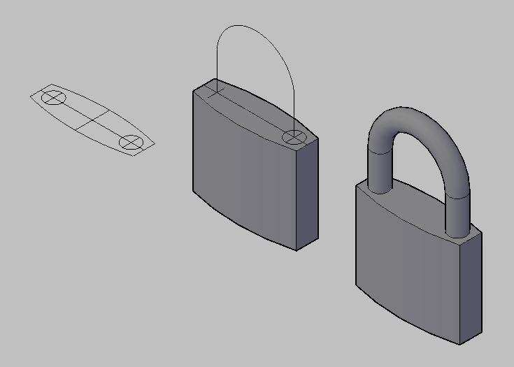 - Here you go. A very basic (small) padlock. Create the body and extrude it (or use PressPull) to give it height. Create a centerline path for the shank and extrude or sweep a circle. That's it. Finished. Go for a beer. ------------- "Humans have a strength that cannot be measured. This is John Connor. If you are reading this, you are the resistance." <<AutoCAD 2015>> |
Posted By: John Connor
Date Posted: 03.Dec.2013 at 12:54
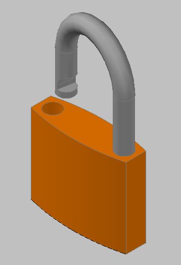 - My new and improved version. The shank has been notched which you can plainly see. What you can't see is the "catch" inside the hole where the shank goes when it is depressed and on the bottom I added the hole for the key. The body of the padlock is on one layer and the shank on another. ------------- "Humans have a strength that cannot be measured. This is John Connor. If you are reading this, you are the resistance." <<AutoCAD 2015>> |
Posted By: John Connor
Date Posted: 03.Dec.2013 at 13:05
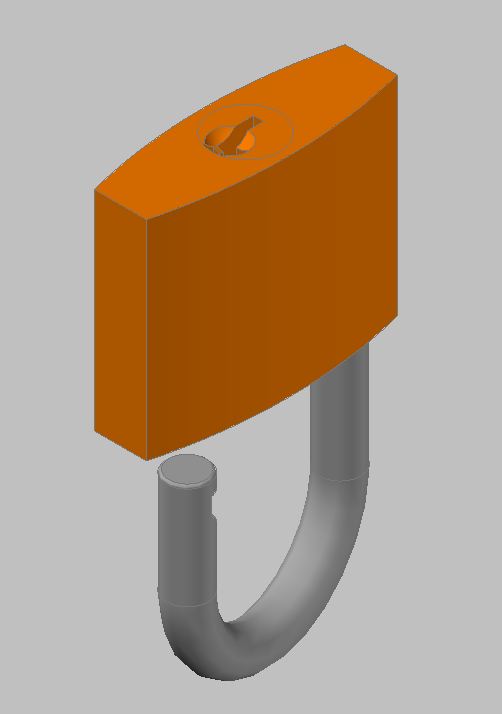 - A view of the bottom. ------------- "Humans have a strength that cannot be measured. This is John Connor. If you are reading this, you are the resistance." <<AutoCAD 2015>> |
Posted By: John Connor
Date Posted: 03.Dec.2013 at 19:16
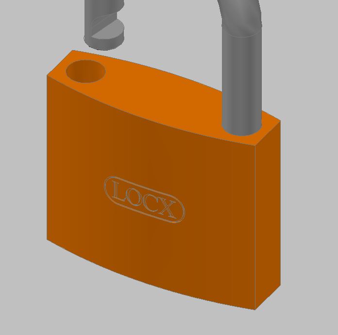 - -Last image. A little branding for my new "LOCX" padlock. The name is cut into the body of the lock. Had to get a bit creative to achieve the final result. Probably a cinch to do in Inventor. AutoCAD...not as easy. ------------- "Humans have a strength that cannot be measured. This is John Connor. If you are reading this, you are the resistance." <<AutoCAD 2015>> |
Posted By: tazlact
Date Posted: 05.Dec.2013 at 03:08
|
Hello John! My son has to do a project for class where he has to show a padlock. the padlock measures are enclosed. If it is possible to do it step by step so he can learn I will appreciate it. Or if you can send it as a file. thanks Luis this is the file http://s25.postimg.org/lpzn5vpi7/Page_1_padlock.jpg" rel="nofollow - http://s25.postimg.org/lpzn5vpi7/Page_1_padlock.jpg |
Posted By: John Connor
Date Posted: 05.Dec.2013 at 11:42
|
I might be able to help if I could read those dimensions but the image is so small I'm having trouble doing so. Anyway, the process is basically as I have shown in the first image I posted. In plan view create the profile of the body. Switch to a SE isometric view and give the profile height using either the Extrude or PressPull command. Create the centerline for the shank using the line and circle command. Trim where necessary. Use the PEdit command to join the two short line segments to the arc (one half of the original circle). Draw a circle equal to the diameter of your shank. Use the Sweep or Extrude command to extrude the circle along a path as defined by your centerline. Make any further additions as required. Of course your son will have to know how to manipulate his view(s) and how to reorient his UCS. I suggest he turn on the UCSICON as a visual reminder or utilize the ViewCube. ------------- "Humans have a strength that cannot be measured. This is John Connor. If you are reading this, you are the resistance." <<AutoCAD 2015>> |
Posted By: John Connor
Date Posted: 05.Dec.2013 at 13:52
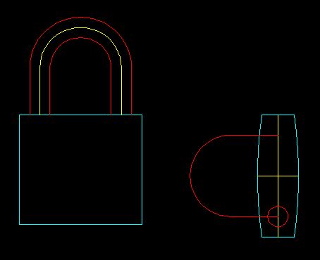 - This is a rough approximation since I could not read the dimensions off your image. Start with a 2D drawing. Set up 3 layers as follows: Body, Color: cyan Shank, Color: red Centerline, Color: yellow ------------- "Humans have a strength that cannot be measured. This is John Connor. If you are reading this, you are the resistance." <<AutoCAD 2015>> |
Posted By: John Connor
Date Posted: 05.Dec.2013 at 13:55
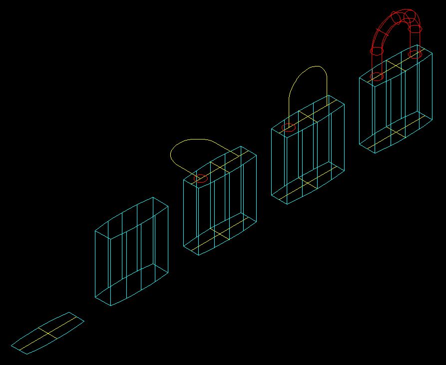 - -The steps for going from 2D to 3D using the Extrude/PressPull and Sweep commands. Visual style: 2Dwireframe. ------------- "Humans have a strength that cannot be measured. This is John Connor. If you are reading this, you are the resistance." <<AutoCAD 2015>> |
Posted By: John Connor
Date Posted: 05.Dec.2013 at 13:58
 - -What it looks like using a Realistic visual style. The body and shank are 3D solids not surfaces. There is a difference. ------------- "Humans have a strength that cannot be measured. This is John Connor. If you are reading this, you are the resistance." <<AutoCAD 2015>> |