![CAD Forum - tips, tricks, discussion and utilities for AutoCAD, Inventor, Revit and other Autodesk products [www.cadforum.cz]](/common/arkance_186.png "CAD Forum - ARKANCE Community - tips, tricks, discussion and utilities for AutoCAD, Inventor, Revit and other Autodesk products [www.cadforum.cz]")
CAD FORUM - TIPS & TRICKS | UTILITIES | DISCUSSION | BLOCKS | SUPPORT | HELP & ADVICE

Over 1.117.000 registered users (EN+CZ).
AutoCAD tips, Inventor tips, Revit tips, Civil tips, Fusion tips.
The new Beam calculator, Spirograph generator and Regression curves in the Converters section.
New AutoCAD 2027 commands and sys.variables

 Discussion forum
?CAD discussions, advices, exchange of experience
 CAD discussion forum - ask any CAD-related questions here, share your CAD knowledge on AutoCAD, Inventor, Revit and other Autodesk software with your peers from all over the world. To start a new topic, choose an appropriate forum.
Please abide by the rules of this forum.
This is a peer-to-peer forum. The forum doesn't replace the official direct technical support provided by ARKANCE for its customers.
How to post questions: register or login, go to the specific forum and click the NEW TOPIC button.


|
 padlock drawing
Post Reply 
|
Page 12> |
| Author | |
zackatt 
Newbie 
Joined: 02.Dec.2013 Location: Puerto Rico Using: autocad2014, autocad 2011 Status: Offline Points: 2 |
 Topic: padlock drawing Topic: padlock drawingPosted: 02.Dec.2013 at 15:28 |
|
new with autocad and the first thing they asked me to do is a padlock 3d drawing and honestly have no idea, please help
|
|
 |
|
|
John Connor
Senior Member 
Joined: 01.Feb.2011 Location: United States Using: AutoCAD 2018 Status: Offline Points: 7175 |
Posted: 02.Dec.2013 at 17:31 |
|
How detailed does it have to be?
Are you showing it opened or closed? See my next post for a quick run down of what it takes to create a simple padlock. There is one other option and that is to find one (in 3D) that someone else already created and use that instead. But that would be cheating now wouldn't it? And you really do want to impress people with your 3D skills so you better do it yourself. Do you have any experience working in 3D? Edited by John Connor - 02.Dec.2013 at 17:48 |
|
|
"Humans have a strength that cannot be measured. This is John Connor. If you are reading this, you are the resistance."
<<AutoCAD 2015>> |
|
|
|
|
John Connor
Senior Member
Joined: 01.Feb.2011 Location: United States Using: AutoCAD 2018 Status: Offline Points: 7175 |
Posted: 02.Dec.2013 at 17:44 |
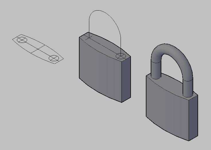 - Here you go. A very basic (small) padlock. Create the body and extrude it (or use PressPull) to give it height. Create a centerline path for the shank and extrude or sweep a circle. That's it. Finished. Go for a beer. Edited by John Connor - 02.Dec.2013 at 17:44 |
|
|
"Humans have a strength that cannot be measured. This is John Connor. If you are reading this, you are the resistance."
<<AutoCAD 2015>> |
|
|
|
|
John Connor
Senior Member
Joined: 01.Feb.2011 Location: United States Using: AutoCAD 2018 Status: Offline Points: 7175 |
Posted: 03.Dec.2013 at 12:54 |
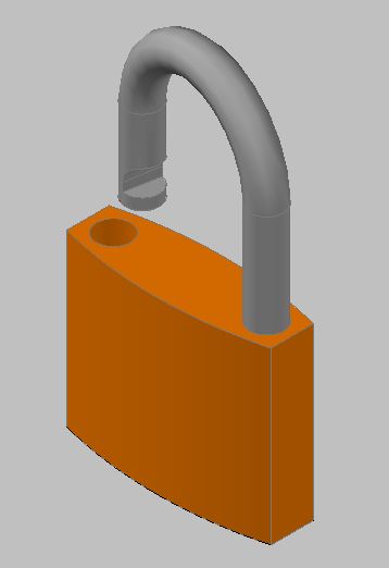 - My new and improved version. The shank has been notched which you can plainly see. What you can't see is the "catch" inside the hole where the shank goes when it is depressed and on the bottom I added the hole for the key. The body of the padlock is on one layer and the shank on another. |
|
|
"Humans have a strength that cannot be measured. This is John Connor. If you are reading this, you are the resistance."
<<AutoCAD 2015>> |
|
|
|
|
John Connor
Senior Member
Joined: 01.Feb.2011 Location: United States Using: AutoCAD 2018 Status: Offline Points: 7175 |
Posted: 03.Dec.2013 at 13:05 |
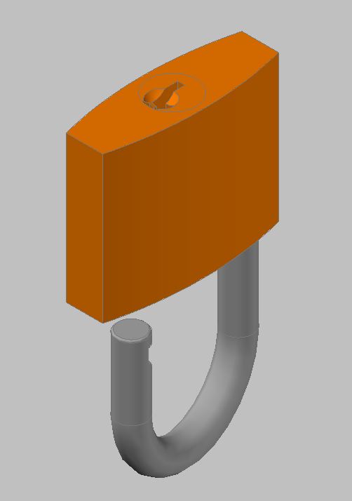 - A view of the bottom. |
|
|
"Humans have a strength that cannot be measured. This is John Connor. If you are reading this, you are the resistance."
<<AutoCAD 2015>> |
|
|
|
|
John Connor
Senior Member
Joined: 01.Feb.2011 Location: United States Using: AutoCAD 2018 Status: Offline Points: 7175 |
Posted: 03.Dec.2013 at 19:16 |
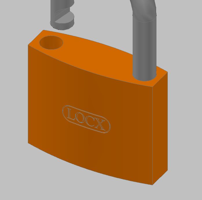 - -Last image. A little branding for my new "LOCX" padlock. The name is cut into the body of the lock. Had to get a bit creative to achieve the final result. Probably a cinch to do in Inventor. AutoCAD...not as easy. |
|
|
"Humans have a strength that cannot be measured. This is John Connor. If you are reading this, you are the resistance."
<<AutoCAD 2015>> |
|
|
|
|
tazlact
Newbie
Joined: 05.Dec.2013 Location: Puerto Rico Using: autocad2014 Status: Offline Points: 1 |
Posted: 05.Dec.2013 at 03:08 |
|
Hello John!
My son has to do a project for class where he has to show a padlock. the padlock measures are enclosed. If it is possible to do it step by step so he can learn I will appreciate it. Or if you can send it as a file. thanks Luis this is the file http://s25.postimg.org/lpzn5vpi7/Page_1_padlock.jpg Edited by tazlact - 05.Dec.2013 at 03:29 |
|
|
|
|
John Connor
Senior Member
Joined: 01.Feb.2011 Location: United States Using: AutoCAD 2018 Status: Offline Points: 7175 |
Posted: 05.Dec.2013 at 11:42 |
|
I might be able to help if I could read those dimensions but the image is so small I'm having trouble doing so.
Anyway, the process is basically as I have shown in the first image I posted. In plan view create the profile of the body. Switch to a SE isometric view and give the profile height using either the Extrude or PressPull command. Create the centerline for the shank using the line and circle command. Trim where necessary. Use the PEdit command to join the two short line segments to the arc (one half of the original circle). Draw a circle equal to the diameter of your shank. Use the Sweep or Extrude command to extrude the circle along a path as defined by your centerline. Make any further additions as required. Of course your son will have to know how to manipulate his view(s) and how to reorient his UCS. I suggest he turn on the UCSICON as a visual reminder or utilize the ViewCube. Edited by John Connor - 05.Dec.2013 at 13:11 |
|
|
"Humans have a strength that cannot be measured. This is John Connor. If you are reading this, you are the resistance."
<<AutoCAD 2015>> |
|
|
|
|
John Connor
Senior Member
Joined: 01.Feb.2011 Location: United States Using: AutoCAD 2018 Status: Offline Points: 7175 |
Posted: 05.Dec.2013 at 13:52 |
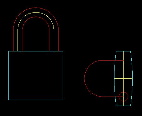 - This is a rough approximation since I could not read the dimensions off your image. Start with a 2D drawing. Set up 3 layers as follows: Body, Color: cyan Shank, Color: red Centerline, Color: yellow |
|
|
"Humans have a strength that cannot be measured. This is John Connor. If you are reading this, you are the resistance."
<<AutoCAD 2015>> |
|
|
|
|
John Connor
Senior Member
Joined: 01.Feb.2011 Location: United States Using: AutoCAD 2018 Status: Offline Points: 7175 |
Posted: 05.Dec.2013 at 13:55 |
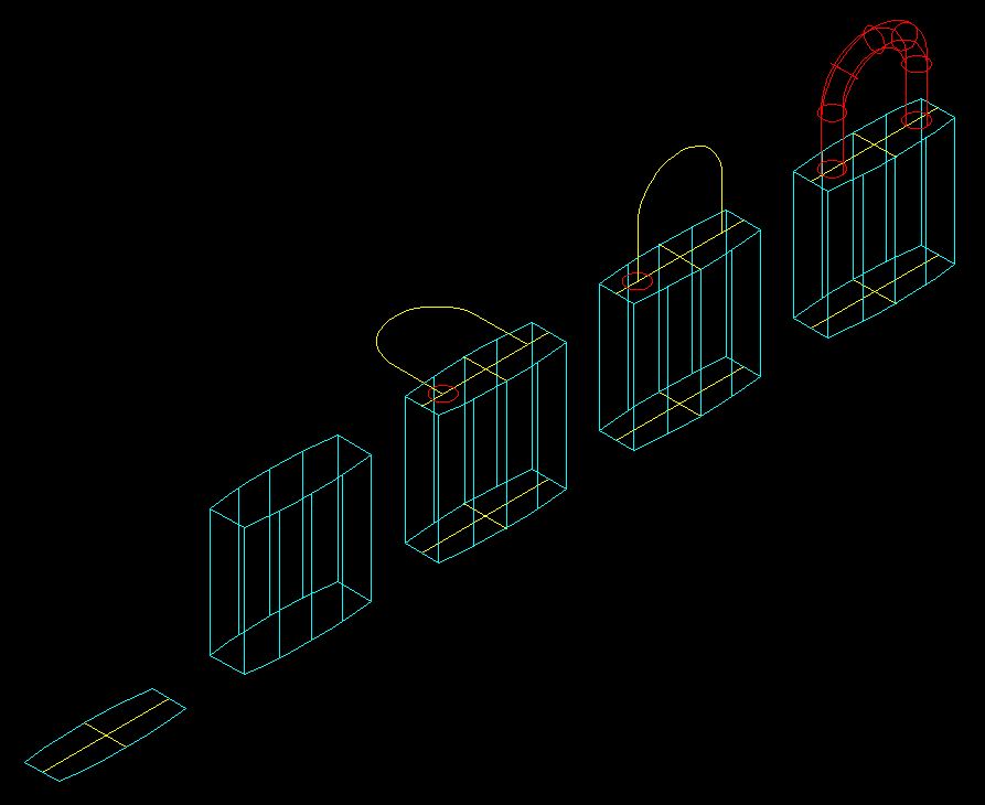 - -The steps for going from 2D to 3D using the Extrude/PressPull and Sweep commands. Visual style: 2Dwireframe. |
|
|
"Humans have a strength that cannot be measured. This is John Connor. If you are reading this, you are the resistance."
<<AutoCAD 2015>> |
|
|
|
 Topic Options
|
Post Reply
|
Page 12> |
 Tweet
Tweet
|
| Forum Jump | Forum Permissions You cannot post new topics in this forum You cannot reply to topics in this forum You cannot delete your posts in this forum You cannot edit your posts in this forum You cannot create polls in this forum You cannot vote in polls in this forum |
This page was generated in 0,184 seconds.

CADforum
Tips and tricks, support, utilities, help, discussions on AutoCAD, LT, Inventor, Revit, Map, Civil 3D, 3ds Max, Fusion, Forma, Vault, PowerMill and other Autodesk software (community support by ARKANCE). See About CADforum.
Copyright © 2026 | Advertise with us | Online privacy
