Over 1.113.000 registered users (EN+CZ).
AutoCAD tips, Inventor tips, Revit tips, Civil tips, Fusion tips.
The new Beam calculator, Spirograph generator and Regression curves in the Converters section.
 CAD tip # 9357:
Question
A
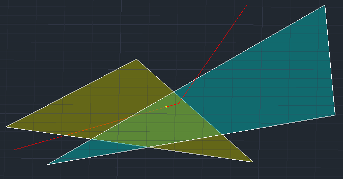
If you want to display (create a point, get XYZ coordinates, trim curve) an intersection of a 3D curve or line and a 3D plane or surface, you can use the following procedure.
When you have got a simple 3D line and a 3D face, you can use the ilp function in AutoCAD geometric calculator - see Tip 4201.
For more complex cases, use an auxiliar construction with projected curve on the given plane or surface.

- If the plane is defined by a 3DFACE, convert it to a region using the REGION command. If the surface is defined by a 3D mesh or similar object, convert it first to a surface with CONVTOSURFACE.
- Switch to a user coordinate system (UCS) defined by the surface plane - on curved surfaces use an approximate projection near the expected intersection point. See e.g. the command UCS with the option obJect.
- Use the PROJECTGEOMETRY command to project the 3D line (polyline, curve) onto the selected surface. If needed, select the view/project direction: "Ucs".
- Now the 3D intersection of the original and the projected curves is the requested intersection point - you can use it to create a point (POINT), get its coordinates (ID), etc. - use the osnap INTerstection to acquire exact coordinates.
NB: in case of a 3D spline, the intersection may not appear - this is a result of different interpolation procedures for 2D (projected) and 3D splines
ACAD
24.7.2013
43349×
this tip shared by ARKANCE experts applies to: AutoCAD ·
![CAD Forum - tips, tricks, discussion and utilities for AutoCAD, Inventor, Revit and other Autodesk products [www.cadforum.cz] CAD Forum - tips, tricks, discussion and utilities for AutoCAD, Inventor, Revit and other Autodesk products [www.cadforum.cz]](../common/arkance_186.png)


