


 CAD tip # 14039:

|
| Question | CAD % platform category |
||||||||
|---|---|---|---|---|---|---|---|---|---|
|
|
||||||||
applies to: AutoCAD · AutoCAD Architecture · AutoCAD Plant 3D · AutoCAD Mechanical · Civil 3D · AutoCAD Map 3D · | |||||||||
") AutoCAD
AutoCAD| See also: | |
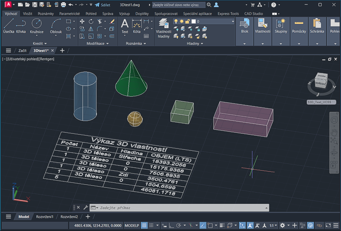
| Tip 13472: | How to convert the structure of a volumetric lattice to a real mesh body? |
| Tip 13227: | Reference Explorer - quick analysis of your project or assembly (file size, xref errors). |
| Tip 13211: | Automatic numbering/renaming of multi-volume bodies in a part. |
| Tip 13013: | Converting a 3D mesh to a 3D solid in Fusion 360. |
| Tip 12771: | Simplification of an assembly in Fusion 360 - the shrinkwrap function |
Have we helped you? If you want to support the CAD Forum web service, consider buying one of our CAD applications, or our custom software development offerings, or donating via PayPal (see above).
You may also add a link to your web - like this "fan" link:
|
|
|
Featuring: Add .CIT raster format support to AutoCAD and Map and Civil 3D CITin 
|
Please use these tips at your own risk.
Arkance Systems is not responsible for possible problems that may occur as a result of using any of these tips.
|
Arkance Systems CZ s.r.o. (CAD Studio) - Autodesk Platinum Partner & Training Center & Consulting Services Partner
|
CONTACT:
webmaster.cz@arkance-systems.com tel. +420 910 970 111 |
||
| Copyright © 2024 | Advertise with us | Online privacy |
| ||
