![CAD Forum - tips, tricks, discussion and utilities for AutoCAD, Inventor, Revit and other Autodesk products [www.cadforum.cz]](../common/arkance_186.png "CAD Forum - tips, tricks, discussion and utilities for AutoCAD, Inventor, Revit and other Autodesk products [www.cadforum.cz]")


 CAD tip # 11751:
Question
The LISP application toMulti can be downloaded from  Download. Unpack the ZIP file (containing the .VLX and .TAB file) to an AutoCAD support path, load the application with APPLOAD and run it by typing the TOMULTI command.
The command prompts to select the polylines and the name of one of the definitions prescribed in the .TAB file (must be accessible in search path). Then it converts selected polylines to multi-lines.
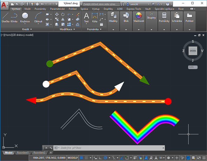
Since version 1.3 you can use layer names with spaces (must be enclosed in double quotes) and RGB color codes (a triplet in parentheses).
; *DefinitionName1
; offset[,color[,width[,linetype[,layer]]]]
; offset[,color[,width[,linetype[,layer]]]]
; [#startBlockName[,#endBlockName]]
; *DefinitionName2
; offset[,color[,width[,linetype[,layer]]]]
; offset[,color[,width[,linetype[,layer]]]]
; offset[,color[,width[,linetype[,layer]]]]
; S|E|B[,color[,width[,linetype[,layer]]]]
; [#startBlockName[,#endBlockName]]
;
; multi-word layer names as "My Layer", RGB colors as (R,G,B) values
;
*Fuskic
0.25,30,0.25
-0.25,30,0.25
0,51,0.25
0,1,0.08,Dashed
#circle,#arrow
*SimpleDup
0.25
-0.25
*CappedDup
0.25,(255,0,0),0,Continuous,Offset1
-0.25,_ByLayer,0,Continuous,"Offset 2"
B,2
The variable DELOBJ controls deletion of the original (control) polyline.
When you set the LISP variable (setq _toMultiGroup T), the resulting lines will be grouped into an anonymous group (selected as one object).

