
CAD discussion forum - ask any CAD-related questions here, share your CAD knowledge on AutoCAD, Inventor, Revit and other Autodesk software with your peers from all over the world. To start a new topic, choose an appropriate forum.
Please abide by the
rules of this forum.
How to post questions: register or login, go to the specific forum and click the NEW TOPIC button.
| Author |
 Topic Search Topic Search  Topic Options Topic Options
|
John Connor 
Senior Member

Joined: 01.Feb.2011
Location: United States
Using: AutoCAD 2018
Status: Offline
Points: 7175
|
 Posted: 16.Mar.2014 at 16:24 Posted: 16.Mar.2014 at 16:24 |
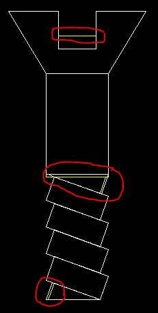 The faint yellow lines are where our two screws differ (circled in red). Like I said, you are very close. A bit of tweaking and you will be there.
|
|
"Humans have a strength that cannot be measured. This is John Connor. If you are reading this, you are the resistance."
<<AutoCAD 2015>>
|
 |
Bobdob
Groupie

Joined: 01.Sep.2013
Location: United Kingdom
Using: About to learn
Status: Offline
Points: 51
|
Posted: 16.Mar.2014 at 16:28 |
 John Connor wrote: John Connor wrote:
You're very close. What seems to be the problem?
|
As you can see, below, I have made a rectangle, chose the dimensions 1.4 width (which the drawing says is the dimension) and chose 3.5 length (which is what I assumed, but did not KNOW was the length), then I chose to rotate it 340 degrees as the drawing says 20 degrees. But then as you can see below, the rectangle does not fit between the horizontal guidelines like it should. Basically I do not know the length of the rectangles and do not know how to find out? 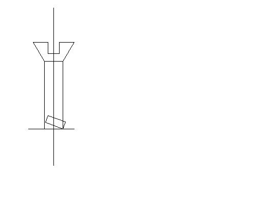
|
|
John Connor
Senior Member
Joined: 01.Feb.2011
Location: United States
Using: AutoCAD 2018
Status: Offline
Points: 7175
|
Posted: 16.Mar.2014 at 16:47 |
|
The 3.5 is not the width of the rectangle. The width has to be shorter.
Anyway, you were so close before why are you redoing it? I think you had the right size for the rectangle originally. Look at the image I posted previously. Our rectangles match.
Unfortunately I have to step away from my computer as I have other "stuff" to do. Keep at it man; I have every confidence in you. You are soooooooo close.
Edited by John Connor - 16.Mar.2014 at 16:49
|
|
"Humans have a strength that cannot be measured. This is John Connor. If you are reading this, you are the resistance."
<<AutoCAD 2015>>
|
|
Bobdob
Groupie
Joined: 01.Sep.2013
Location: United Kingdom
Using: About to learn
Status: Offline
Points: 51
|
Posted: 16.Mar.2014 at 17:00 |
 Thanks mate, I'll try. I think I nearly got it right before because I just lengthened the rectangles and I know that is no way to do it, I want to do it the 'right' way. That means finding out the dimensions of the rectangle. I've just seen that the exercise says that the width is 1.4 so I just have to get the length.....but cant without lengthening them...  PS- I'll post the bike video later.
|
|
Bobdob
Groupie
Joined: 01.Sep.2013
Location: United Kingdom
Using: About to learn
Status: Offline
Points: 51
|
Posted: 16.Mar.2014 at 17:15 |
JC, neither of these cut off points (in red) seem to correlate perfectly with the drawing exercise I have? 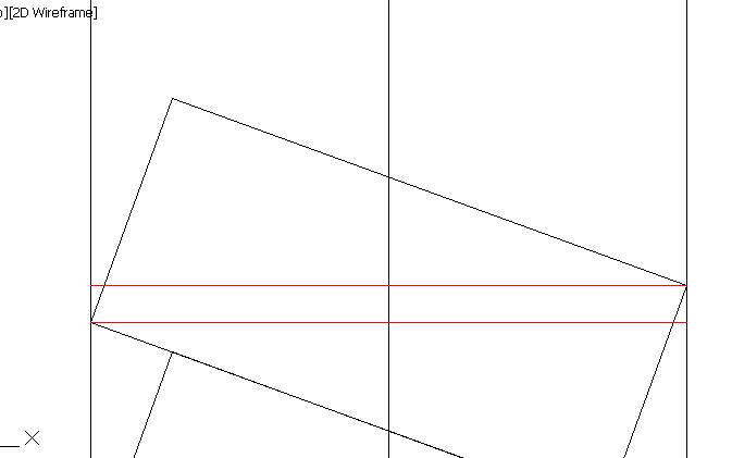
|
|
Bobdob
Groupie
Joined: 01.Sep.2013
Location: United Kingdom
Using: About to learn
Status: Offline
Points: 51
|
Posted: 16.Mar.2014 at 20:51 |
I've just started from scratch and come up against the same problem again, where to cut it off. The cut off line does not correlate with the exercise?: 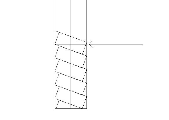
|
|
John Connor
Senior Member
Joined: 01.Feb.2011
Location: United States
Using: AutoCAD 2018
Status: Offline
Points: 7175
|
Posted: 16.Mar.2014 at 21:43 |
Bobdob wrote:
JC, neither of these cut off points (in red) seem to correlate perfectly with the drawing exercise I have?
|
Use the lower of the two lines.
|
|
"Humans have a strength that cannot be measured. This is John Connor. If you are reading this, you are the resistance."
<<AutoCAD 2015>>
|
|
Bobdob
Groupie
Joined: 01.Sep.2013
Location: United Kingdom
Using: About to learn
Status: Offline
Points: 51
|
Posted: 16.Mar.2014 at 22:06 |
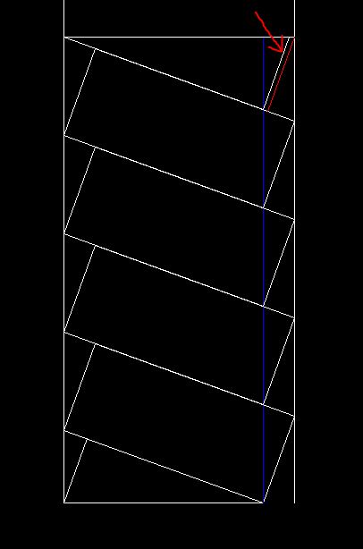
Hi JC, But you see where I have highlighted in red, below, is so different to what we would see if I chose the bottom red line on mine: 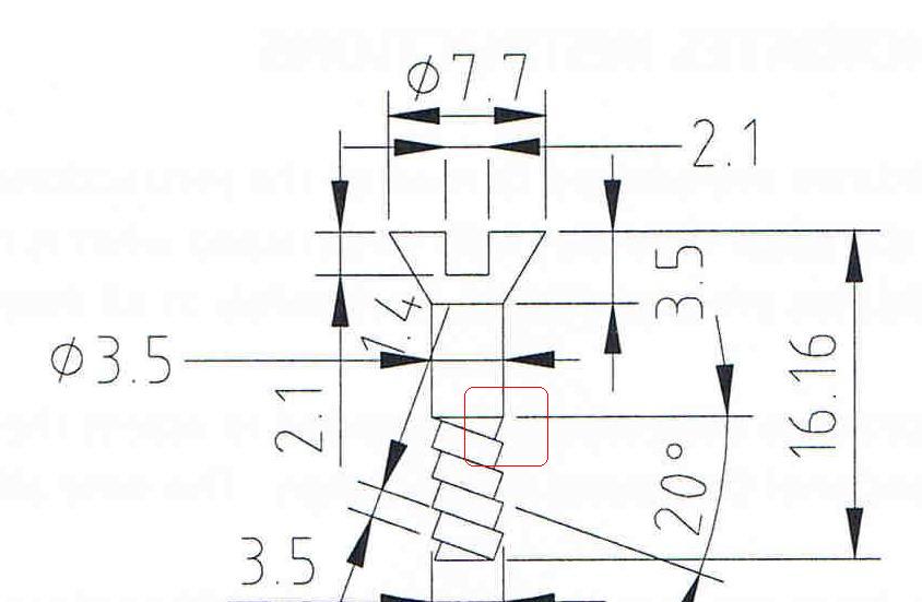 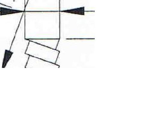 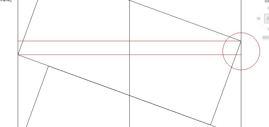 Do you see what I mean?
|
|
John Connor
Senior Member
Joined: 01.Feb.2011
Location: United States
Using: AutoCAD 2018
Status: Offline
Points: 7175
|
Posted: 17.Mar.2014 at 10:58 |
 . The distance between the two vertical white lines is 3.5. The blue vertical line represents the lower right hand corner of our rectangle. The white diagonal line at the top represents where the partial rectangle should be. The red diagonal line is where the line is drawn in the diagram. The difference between the two diagonal lines is 0.0739. If you were looking at the drawing after it was printed you would not know the red line was in the wrong position. My advice...put the line where your teacher expects to see it based on the diagram and move on unless you have a mop of hair that rivals a sheepdog. Otherwise you'll spend 1 hour doing the drawing and 16 hours worrying over it.
Edited by John Connor - 17.Mar.2014 at 10:59
|
|
"Humans have a strength that cannot be measured. This is John Connor. If you are reading this, you are the resistance."
<<AutoCAD 2015>>
|
|
Kent Cooper
Senior Member
Joined: 12.Mar.2013
Location: United States
Using: AutoCAD2020, 2023
Status: Offline
Points: 632
|
Posted: 17.Mar.2014 at 14:12 |
If the corners of the tilted rectangle are supposed to align across one red line, use the ALIGN command, aligning the diagonally opposite corners of the rectangle with the ends of one red line, and answering Yes to the question of scaling the result.
But it seems a little strange to put a lot of detailed effort into getting something that does not look very much like real screw threads at all to be "just right." And has anyone else noticed that it's reverse-threaded? Is it supposed to be? Something like this, while not really completely correct either, would be a whole lot closer.
|
|


 Discussion forum


 Mock exam in College-Need a little help please?

 Tweet
Tweet
