


 Discussion forum
|

 CAD discussion forum - ask any CAD-related questions here, share your CAD knowledge on AutoCAD, Inventor, Revit and other Autodesk software with your peers from all over the world. To start a new topic, choose an appropriate forum.
Please abide by the rules of this forum.
How to post questions: register or login, go to the specific forum and click the NEW TOPIC button.


|
 What Kind of Projection Is This?
Post Reply 
|
Page 12> |
| Author | |
philippe JOSEPH 
Senior Member 
Joined: 14.Mar.2011 Location: France Using: AutoCAD Mechanical 2017 Status: Offline Points: 1426 |
 Topic: What Kind of Projection Is This? Topic: What Kind of Projection Is This?Posted: 19.Oct.2019 at 18:35 |
|
Yes John the "drawing" is 2D but I hope that the informatic work was done in 3D and not with the "like on the drawing board old way".
I have never really done 2D isometric drawing or only for scheme or pipings with symbols but now with the "real" 3D we can do all this better and quicker. The level of detail shown on the drawings makes me think that it's real 3D. Eventually see my AutoCAD file : in the CAD/BIM Blocks library done in answer of a cad discussion. I had realized a 2D isometric drawing from an image file by doing real 3D solids and then FLATSHOT it.
Edited by philippe JOSEPH - 19.Oct.2019 at 18:37 |
|
 |
|
|
John Connor
Senior Member
Joined: 01.Feb.2011 Location: United States Using: AutoCAD 2018 Status: Offline Points: 7175 |
Posted: 19.Oct.2019 at 14:59 |
|
I never though the drawing was 3D. Always looked 2D to me.
|
|
|
"Humans have a strength that cannot be measured. This is John Connor. If you are reading this, you are the resistance."
<<AutoCAD 2015>> |
|
|
|
|
philippe JOSEPH
Senior Member
Joined: 14.Mar.2011 Location: France Using: AutoCAD Mechanical 2017 Status: Offline Points: 1426 |
Posted: 19.Oct.2019 at 08:08 |
|
And the answer is : ........................................................................ TRIMETRIC...........................................................
|
|
|
|
|
philippe JOSEPH
Senior Member
Joined: 14.Mar.2011 Location: France Using: AutoCAD Mechanical 2017 Status: Offline Points: 1426 |
Posted: 18.Oct.2019 at 22:39 |
|
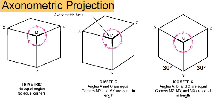
Dery, if you do a search on the internet you will find the various projections : isometric, dimetric with their diffrerent settings on the angles and length ( dimetric = 2 angles and length are equal, isometric = 3 angles and length are equal ).
The drawings are not isometric and not dimetric but from a 3D point of view ( isometric modified to see better the elements ). Is your work 2D or 3D, I hope it's 3D because is now less work than the old way to draw.
 Edited by philippe JOSEPH - 18.Oct.2019 at 22:46 |
|
|
|
|
dery
Senior Member
Joined: 31.Jan.2018 Location: United States Using: AutoCAD 2014 Status: Offline Points: 111 |
Posted: 18.Oct.2019 at 20:41 |
What do you mean by "2D isometric view using dimetric projection"? I don't understand. Do you mean the projection is combined? Clearly it can be seen that the drawing is not isometric projection.
Edited by dery - 18.Oct.2019 at 20:46 |
|
|
|
|
dery
Senior Member
Joined: 31.Jan.2018 Location: United States Using: AutoCAD 2014 Status: Offline Points: 111 |
Posted: 18.Oct.2019 at 20:38 |
That's why ask the question because it does not look like an isometric projection to me.
|
|
|
|
|
philippe JOSEPH
Senior Member
Joined: 14.Mar.2011 Location: France Using: AutoCAD Mechanical 2017 Status: Offline Points: 1426 |
Posted: 18.Oct.2019 at 20:17 |
|
Valid for everybody : See the related CAD tip N° 4793:Dimetry - dimetric projection of AutoCAD 3D objects.
|
|
|
|
|
philippe JOSEPH
Senior Member
Joined: 14.Mar.2011 Location: France Using: AutoCAD Mechanical 2017 Status: Offline Points: 1426 |
Posted: 18.Oct.2019 at 18:10 |
|
In fact The angle "A" is greater than the angle "C" and you can check it for example by redrawing an object with a paper on your screen and measuring the angles or rotating that paper for a check on the other angle.
|
|
|
|
|
philippe JOSEPH
Senior Member
Joined: 14.Mar.2011 Location: France Using: AutoCAD Mechanical 2017 Status: Offline Points: 1426 |
Posted: 18.Oct.2019 at 17:58 |
|
OK John and dery but I don't see equal the 2 angles "A" and "C".
If it's a 3D point of view 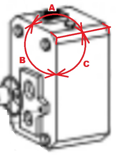 on a 3D object, how can we set the DDVIEWPOINT angles to have a good dimetric view ? |
|
|
|
|
John Connor
Senior Member
Joined: 01.Feb.2011 Location: United States Using: AutoCAD 2018 Status: Offline Points: 7175 |
Posted: 18.Oct.2019 at 17:18 |
|
I believe it could very well be a 2D isometric view using dimetric projection.
|
|
|
"Humans have a strength that cannot be measured. This is John Connor. If you are reading this, you are the resistance."
<<AutoCAD 2015>> |
|
|
|

 Topic Options
 John Connor wrote:
|
Post Reply
|
Page 12> |
 Tweet
Tweet
|
| Forum Jump | Forum Permissions You cannot post new topics in this forum You cannot reply to topics in this forum You cannot delete your posts in this forum You cannot edit your posts in this forum You cannot create polls in this forum You cannot vote in polls in this forum |
This page was generated in 0,433 seconds.
|
CAD Forum - tips, tricks, utilities, discussion for AutoCAD, LT, Inventor, Revit, Map, Civil 3D, 3ds Max, Fusion 360 and other Autodesk software (support by Arkance Systems)
|
Arkance Systems CZ (CAD Studio) - Autodesk Platinum Partner & Training Center & Services Partner
|
CONTACT:
webmaster.cz@arkance-systems.com tel. +420 910 970 111 |
|
| Copyright ©2024 | Advertise with us | Online privacy |
| ||
