![CAD Forum - tips, tricks, discussion and utilities for AutoCAD, Inventor, Revit and other Autodesk products [www.cadforum.cz]](../common/arkance_186.png "CAD Forum - tips, tricks, discussion and utilities for AutoCAD, Inventor, Revit and other Autodesk products [www.cadforum.cz]")

 CAD tip # 11054:
Question
If you have AutoCAD Civil 3D, it is just a matter of running the right standard function for such calculation. But if you have just a plain AutoCAD, such task is not easy to solve.
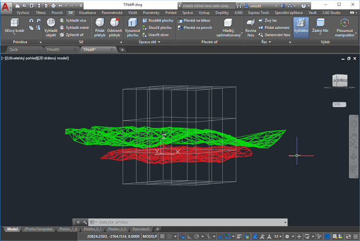
Let's have a two sets of point coordinates, describing the existing (old) and planned (new) terrain surface. First you will need to create a 3D surface from these points. Again, just a snap in AutoCAD Civil 3D; but in plain AutoCAD you will need an add-on tool - e.g. the DTM freeware LISP utility by CAD Studio (ARKANCE) (see also the Tip 5934). Its command DTM will help you make the TIN surfaces (3DFACES) from the individual point sets - here the random (DTMRND command) green and red surfaces (colored manually, recommended to put into separate layers for easier selection):
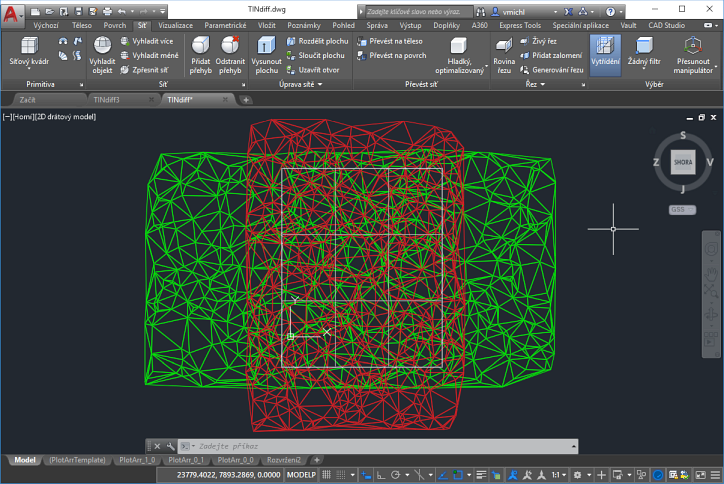
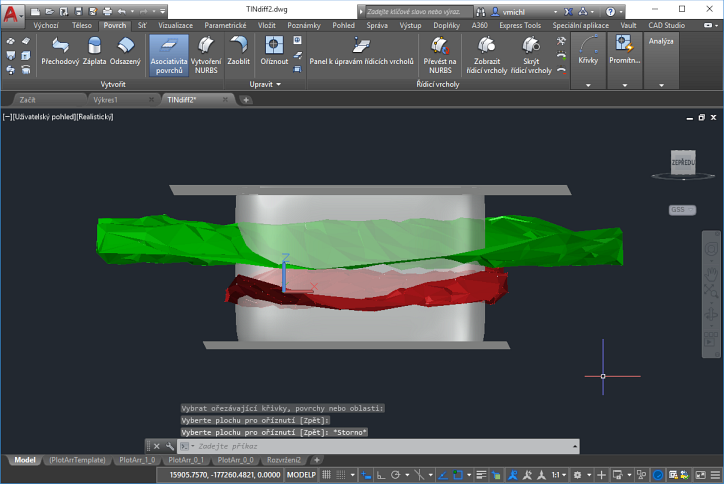
To calculate the volume between two surfaces, we need to "normalize" their shape - they should share the same border exactly (in the plan view) so that the total volume can be calculated as a sum of the individual prisms between the surfaces. In most cases, this means you need to trim one or both terrain surfaces - either by extruding the border curve of the smaller of them, or by creating an auxiliar "trimming" 3D box (prism). We will also need to make AutoCAD "Surface" objects from all these components to finally generate the resulting 3D solid and read its volume.
Draw the trimming box with the MESH Box command (or extrude any polyline to a 3D mesh). You can draw it in the plane view and use the .XY point filters - specify the Z coordinate to make the box with sufficient height. See the resulting white semitransparent object. Convert this box and both terrains to Surface objects with the command CONVTOSURFACE. Select all terrain triangles (3DFACES) of the particular terrain.

You may want to delete the old 3DFACEs and maybe also the control POINTs - use the QSELECT filter to do this.
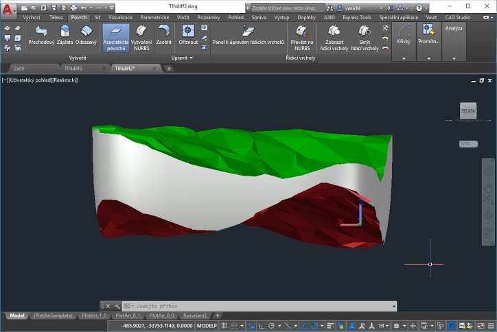
Now we have to prepare the "sides" and "top" and "bottom" part of the future 3D solid. For this, we have to cut the existing top and bottom planes of the trim-box (prism). Use the PLANESURF command to draw an auxiliar plane surface and copy it (grips) above the top terrain and below the bottom terrain, so that it still cuts the box:
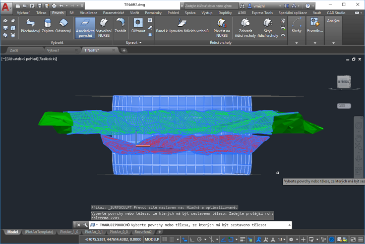
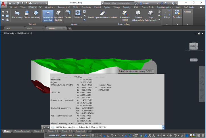
The last part of the procedure is "sculpting" the 3D Solid. Start the command SURFSCULPT and select the trimmed box (prism; without the trimming planes) and both terrains (window select) on its prompt: