![CAD Forum - tips, tricks, discussion and utilities for AutoCAD, Inventor, Revit and other Autodesk products [www.cadforum.cz]](/common/arkance_186.png "CAD Forum - ARKANCE Community - tips, tricks, discussion and utilities for AutoCAD, Inventor, Revit and other Autodesk products [www.cadforum.cz]")
CAD FORUM - TIPS & TRICKS | UTILITIES | DISCUSSION | BLOCKS | SUPPORT | HELP & ADVICE

Over 1.121.000 registered users (EN+CZ).
AutoCAD tips, Inventor tips, Revit tips, Civil tips, Fusion tips.
The new Beam calculator, Spirograph generator and Regression curves in the Converters section.
New AutoCAD 2027 commands and sys.variables


 Discussion forum
?CAD discussions, advices, exchange of experience
 CAD discussion forum - ask any CAD-related questions here, share your CAD knowledge on AutoCAD, Inventor, Revit and other Autodesk software with your peers from all over the world. To start a new topic, choose an appropriate forum.
Please abide by the rules of this forum.
This is a peer-to-peer forum. The forum doesn't replace the official direct technical support provided by ARKANCE for its customers.
How to post questions: register or login, go to the specific forum and click the NEW TOPIC button.


What Drawing This Is? |
Post Reply 
|
| Author | |
teknol 
Newbie 
Joined: 01.May.2026 Location: United States Status: Offline Points: 2 |
 Post Options Post Options
") Thanks(0) Thanks(0)
 Quote Reply Quote Reply
 Topic: What Drawing This Is? Topic: What Drawing This Is?Posted: 01.May.2026 at 18:45 |
|
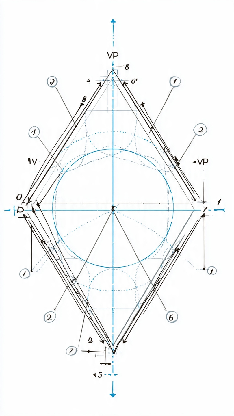
Can anyone tell me please what drawing is this, what it's used for, and how to make and use it in Autocad? Thanks.
|
|
 |
|
|
philippe JOSEPH
Senior Member 
Joined: 14.Mar.2011 Location: France Using: AutoCAD Mechanical 2017 Status: Offline Points: 1524 |
Post Options
Thanks(0)
Quote Reply
Posted: 05.May.2026 at 07:06 |
|
Hello teknol, were did you find this drawing ?
This drawing doesn't include the necessary dimensions to draw it on AutoCAD.
|
|
|
|
|
simutecra
Newbie
Joined: 05.May.2026 Location: United States Using: AutoCAD 2023, SolidWorks 2025 Status: Offline Points: 4 |
Post Options
Thanks(0)
Quote Reply
Posted: 05.May.2026 at 09:54 |
|
This is a geometric construction / engineering drawing, specifically it looks like a descriptive geometry layout used to define relationships between shapes (likely a circle inside a rotated square/diamond with projection lines). You’ll often see this in:
What it’s used forIt’s mainly used to:
How to make it in AutoCADYou don’t draw this as a single command, it’s built step by step:
How it’s “used” in practiceIn real CAD work, this type of drawing is more of a planning/understanding tool rather than something you deliver. Once you understand the geometry, you’d typically:
|
|
|
Simutecra
|
|
|
|
 Topic Options
|
Post Reply
|
|
 Tweet
Tweet
|
| Forum Jump | Forum Permissions You cannot post new topics in this forum You cannot reply to topics in this forum You cannot delete your posts in this forum You cannot edit your posts in this forum You cannot create polls in this forum You cannot vote in polls in this forum |
This page was generated in 0,108 seconds.

CADforum
Tips and tricks, support, utilities, help, discussions on AutoCAD, LT, Inventor, Revit, Map, Civil 3D, 3ds Max, Fusion, Forma, Vault, PowerMill and other Autodesk software (community support by ARKANCE). See About CADforum.
Copyright © 2026 | Advertise with us | Online privacy
