![CAD Forum - tips, tricks, discussion and utilities for AutoCAD, Inventor, Revit and other Autodesk products [www.cadforum.cz]](../common/arkance_186.png "CAD Forum - tips, tricks, discussion and utilities for AutoCAD, Inventor, Revit and other Autodesk products [www.cadforum.cz]")
CAD FORUM - TIPS & TRICKS | UTILITIES | DISCUSSION | BLOCKS | SUPPORT | HELP & ASSISTANCE

Over 1.099.000 registered users (EN+CZ).
AutoCAD tips, Inventor tips, Revit tips.
Try the new precise Engineering calculator and the updated Barcode generator.
New AutoCAD 2026 commands and variables.
 CAD tip # 14443:
Question
A
If you need to display a certain symbol in an AutoCAD polyline outline at specific points, e.g. a connector, a type designation of an assembly point or a notch or cutout interrupting the curve, it is often necessary at the same time to preserve the original shape of the polyline - e.g. for export to a cutting machine, for length and area reports, etc.
These conflicting requirements can be quite easily resolved by combining a dynamic block with automatic alignment and a wipeout object.
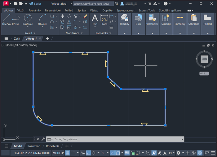
The result can then look like this:
The DWG block Notch.dwg used in the video can be downloaded from the CAD library - Notch.dwg.
There are several rules to follow when creating and using a dynamic block like this:
- in addition to the block shape graphic itself, you need to include a Wipeout entity in the block definition, with a similar shape to the block (preferably with a small overlap) - this will wipe-out the original polyline geometry
- in the block editor, use the Draworder command to place the wipeout "under" the block geometry
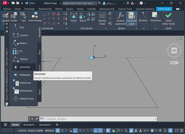
- add the Align parameter to your block (BEDIT), tangent to the detected geometry on block insertion (see the picture)
- when using the block, the FRAME variable must be set to 0 so that the wipeout boundary is not displayed or printed
- use the osnap (e.g. "nearest") to pick the exact insertion point on the curve; the "flip" of the inserted block is affected by the direction from which you approach the curve
Even after such distortions and breaks, the internal shape and properties of the original outline polyline remain intact:
ACADADTPlantACADMCivilMapACLT
6.3.2025
3227×
applies to: AutoCAD · AutoCAD Architecture · AutoCAD Plant 3D · AutoCAD Mechanical · Civil 3D · AutoCAD Map 3D · AutoCAD LT ·


CADforum
Tips, tricks, utilities, help, how-tos and FAQ for AutoCAD, LT, Inventor, Revit, Map, Civil 3D, Fusion, Forma, 3ds Max and other Autodesk software (community support by ARKANCE). See About CADforum.
Copyright © 2025 | Advertise with us | Online privacy